Pressure detecting apparatus having solenoid valve and pressure sensor

a technology of pressure sensor and solenoid valve, which is applied in the direction of valve operating means/release devices, machines/engines, instruments, etc., can solve the problems of semiconductor pressure detecting elements not being suitable for detecting fluid at high temperature, increasing manufacturing costs due to additional components, and large mounting space, etc., to reduce detecting errors

Inactive Publication Date: 2005-09-22
DENSO CORP
View PDF7 Cites 24 Cited by
  • Summary
  • Abstract
  • Description
  • Claims
  • Application Information

AI Technical Summary

Benefits of technology

[0014] In view of the foregoing problems, it is an object of the present invention to produce a secondary air pressure detecting apparatus that is capable of detecting pressure of secondary air in a solenoid valve while reducing detecting error by protecting a pressure sensor from heat transmitting from an exhaust system of an internal combustion engine.

Problems solved by technology

Besides, a mounting space becomes large due to an additional mass of the pressure sensor 101.
Thus, when the pressure sensor 101 is additionally provided to the solenoid secondary-air control valve shown in FIG. 4, manufacturing cost may increase due to additional components and due to additional manufacturing processes.
The semiconductor pressure detecting element is apt to cause a measurement error due to variation in temperature, accordingly, the semiconductor pressure detecting element is not suitable for detecting fluid in high temperature.
The foreign matters may adhere onto the amplifier circuit, which is exposed to the inside the fluid introducing chamber, and the amplifier circuit may output an abnormal signal.
As a result, manufacturing cost increases due to increase of the number of components and manufacturing processes.
As a result, a female connector, which is provided to the tip end of a wire harness on the side of a control apparatus, may not be connected with the male connector.

Method used


Image

  • Pressure detecting apparatus having solenoid valve and pressure sensor
  • Pressure detecting apparatus having solenoid valve and pressure sensor
  • Pressure detecting apparatus having solenoid valve and pressure sensor

Examples


first embodiment

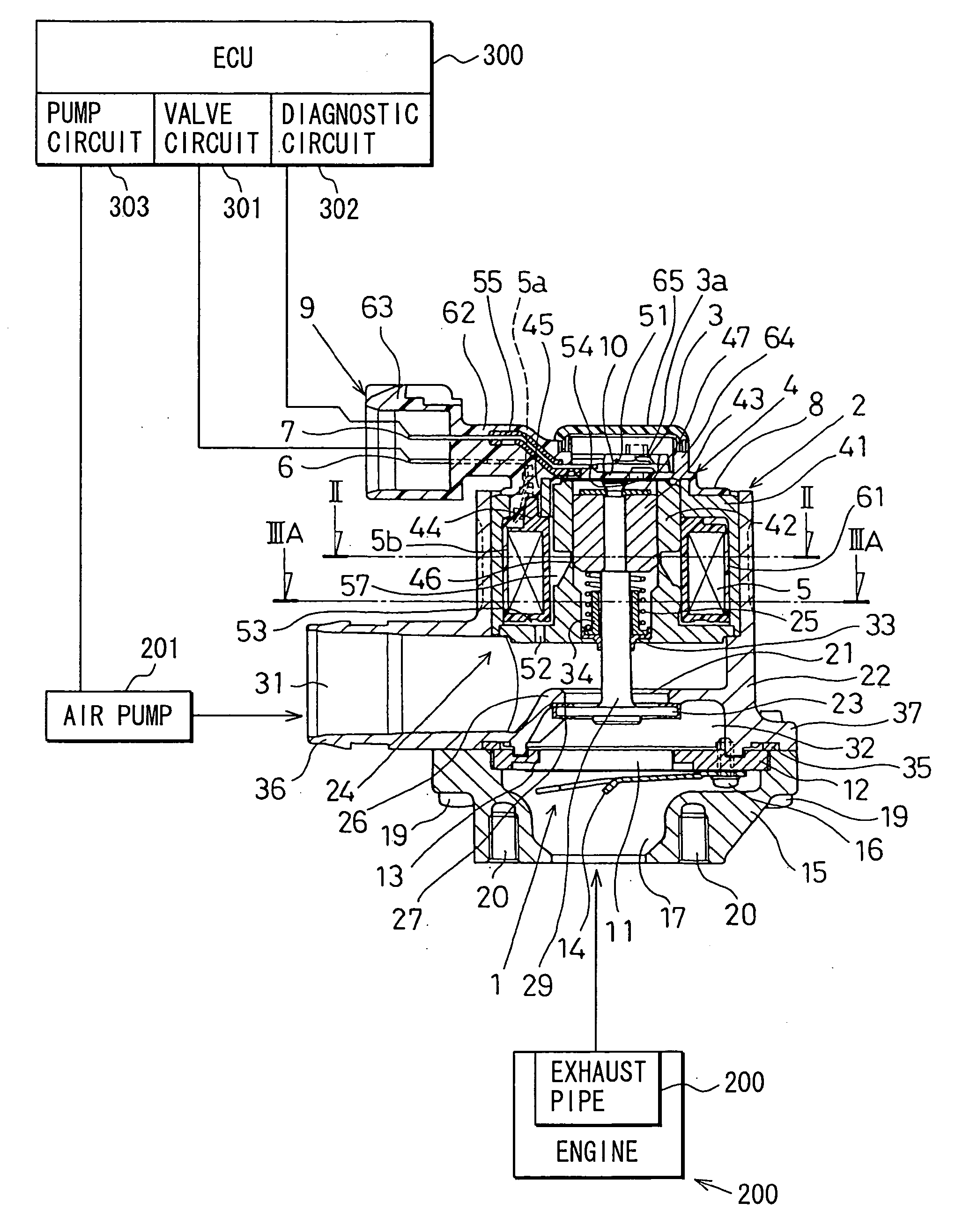
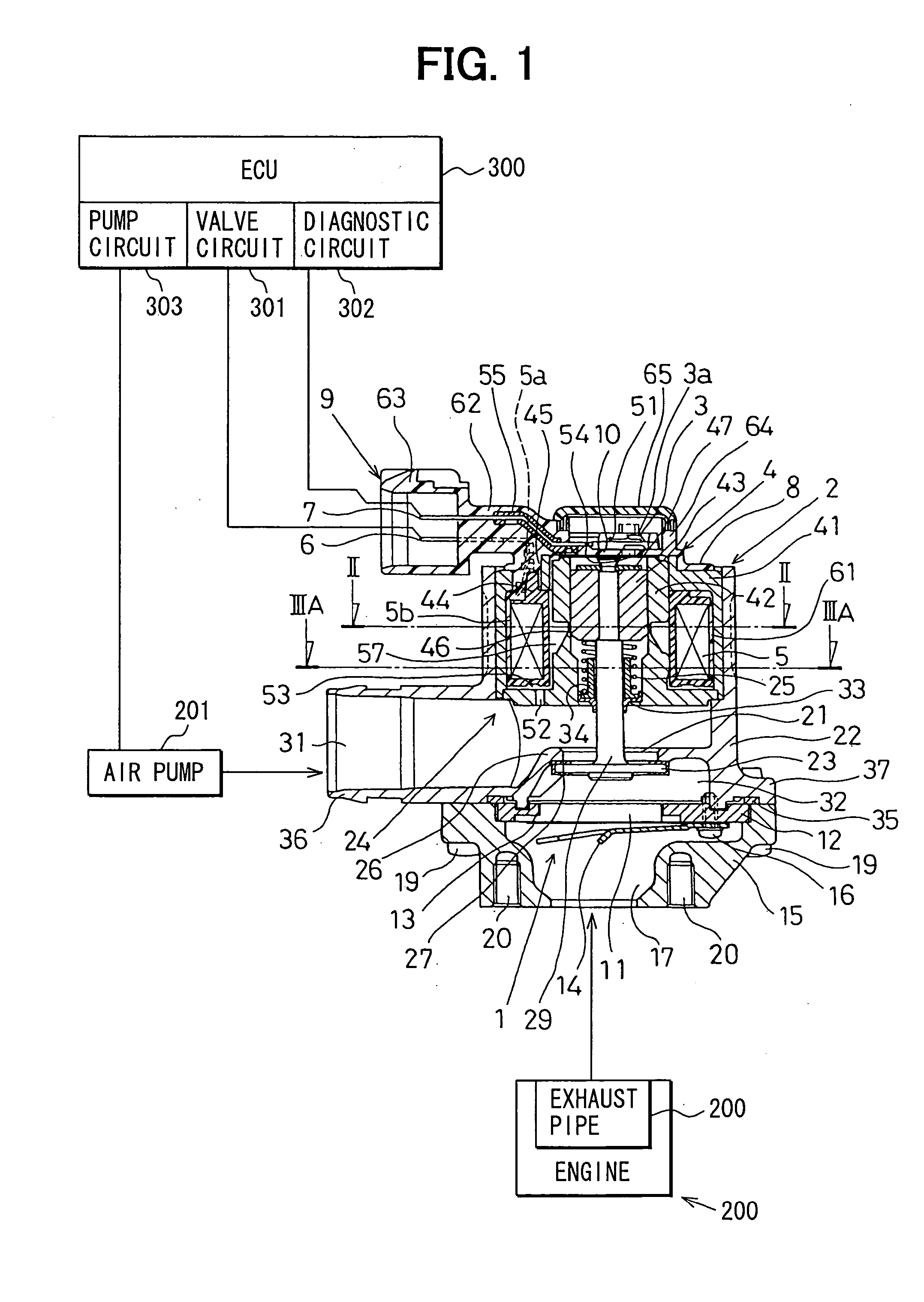
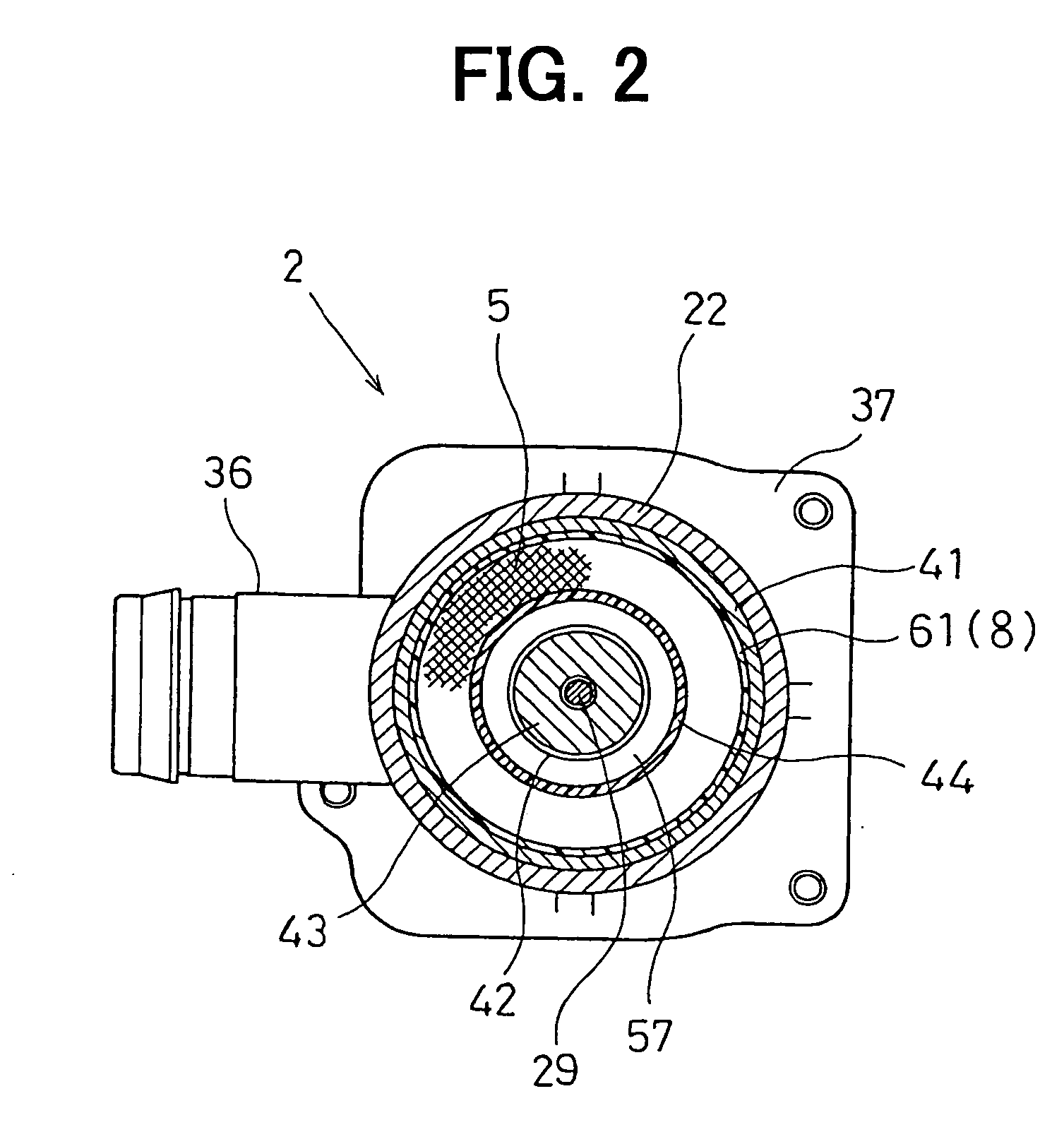
[0029] As shown in FIGS. 1 to 3B, a secondary air supply apparatus includes an air pump 201, an electric motor (not shown), a secondary air passage, a solenoid secondary-air control valve, and an engine control unit (ECU, external circuit) 300. The air pump 201 generates secondary air. The electric motor rotates the air pump 201. The secondary air passage connects the air pump 201 with an exhaust system 202 such as an exhaust pipe 202 of an internal combustion engine 200. The solenoid secondary-air control valve is arranged in an intermediate portion of the secondary air passage, which introduces secondary air into a three-way catalyst converter, so that the solenoid secondary-air control valve opens and closes the secondary air passage. The ECU 300 electronically controls the electric motor and the solenoid secondary-air control valve in accordance with an operating condition of an engine 200.

[0030] The secondary air supply apparatus is connected between a secondary air supply pip...


PUM

PropertyMeasurementUnit
temperatureaaaaaaaaaa
pressureaaaaaaaaaa
magnetic forceaaaaaaaaaa

Abstract

A secondary air pressure detecting apparatus includes a solenoid valve and a pressure sensor. The solenoid valve defines a secondary air passage that introduces secondary air from the air pump into the exhaust system of an engine. The solenoid valve opens and closes the secondary air passage. The pressure sensor is integrally mounted to the solenoid valve to detect pressure of secondary air in the solenoid valve. The solenoid valve includes a coil assembly and magnetic members. The coil assembly includes a solenoid coil that generates magnetic force when the solenoid coil is energized. The magnetic members construct a magnetic circuit with the solenoid coil. The magnetic circuit is arranged outside of the secondary air passage. The pressure sensor is arranged on an opposite side of the secondary air passage with respect to the magnetic circuit.

Description

CROSS REFERENCE TO RELATED APPLICATIONS [0001] This application is based on and incorporates herein by reference Japanese Patent Application No. 2004-75241 filed on Mar. 16, 2004. FIELD OF THE INVENTION [0002] The present invention relates to a secondary air pressure detecting apparatus that includes a solenoid secondary-air control valve, which is constructed of a solenoid valve integrated with a pressure sensor. The solenoid valve opens and closes a secondary air passage, through which secondary air is introduced from an air pump into a three-way catalyst, and the pressure sensor detects secondary air pressure in the solenoid valve. [0003] More particularly, the present invention relates to a secondary air pressure detecting apparatus that detects a failure such as a disorder of an air pump and sticking of the solenoid valve in a closed position. BACKGROUND OF THE INVENTION [0004] Conventionally, when an internal combustion engine is started and exhaust gas emitted from the engine...

Claims


Application Information

Patent Timeline
Patent Type & Authority Applications(United States)
IPC IPC(8): F01N3/10G01L19/00F01N3/22F01N3/32F16K31/06
CPCF01N3/22F01N3/222Y02T10/20F01N2550/14F01N2560/08F01N3/32Y10T137/5762Y02T10/12
Inventor KOUZU, TAKAHIROKOMIYAMA, TADASHI
Owner DENSO CORP
Why Eureka
Try Eureka