Method and apparatus for an acoustic pulse decay density determination

a decay density and acoustic pulse technology, applied in the field of fluid density measurement, to achieve the effect of improving the accuracy of measuremen

Active Publication Date: 2005-09-22
BAKER HUGHES INC
View PDF23 Cites 28 Cited by
  • Summary
  • Abstract
  • Description
  • Claims
  • Application Information

AI Technical Summary

Benefits of technology

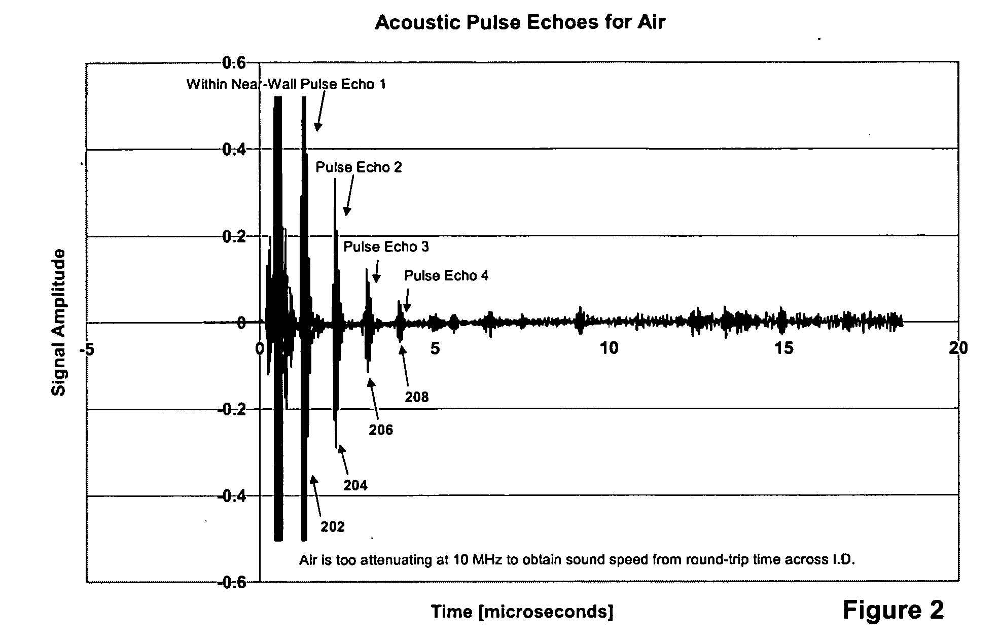
[0010] As the acoustic pulse bounces back and forth within the near wall, each echo of this original pulse loses the same fraction of energy on each round trip. That is, the energy contained within each successive echo decays exponentially. Therefore, we plot the logarithm of the energy in each pulse packet against echo number and calculate the slope. The process of calculating a least-squares-fit slope over many points averages out any small random errors in the individual points being used and so improves the accuracy of the measurement compared to a single-point measurement.

Problems solved by technology

Also, the distribution of reflected energy between the largest amplitude cycle and its neighboring cycles within the same pulse is not constant but changes from pulse to pulse and reflection to reflection, which could be a significant source of inaccuracy in the '693 measurement.

Method used


Image

  • Method and apparatus for an acoustic pulse decay density determination
  • Method and apparatus for an acoustic pulse decay density determination
  • Method and apparatus for an acoustic pulse decay density determination

Examples


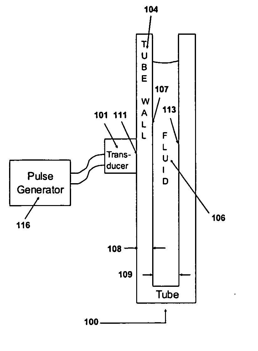
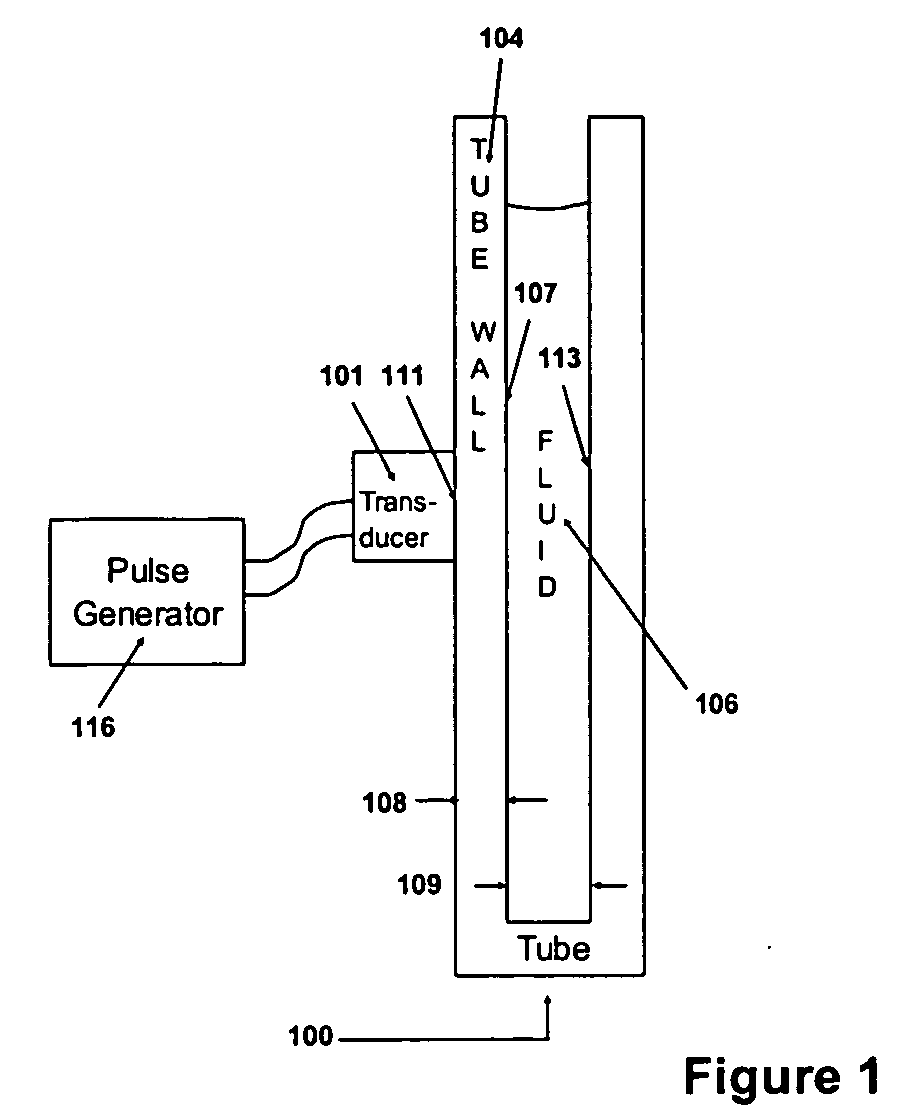
Embodiment Construction

[0028] The present invention provides a method and apparatus for a real time downhole fluid density measurement. The invention is applicable to the determination of fluid density for use in association with wire line and monitoring while drilling applications.

[0029] Turning now to FIG. 1, in a laboratory simulation of the present invention, a small 10 MHz transducer 101 was attached to the outside wall 102 of a titanium alloy sample tube 100. As shown in FIG. 1, the sample tube 100 had dimensions of 0.218″ internal diameter 109 and walls of 0.110″ thickness 108. After the transducer 101 was pulsed, acoustic reflections 202, 204, 206 and 208 were monitored using this same transducer 101. The laboratory validation experiment was performed having different substances 106 filling the sample tube. The experiment was performed for air, oil, and water filling the tube. These experiments are as shown in FIGS. 2, 3, and 4 respectively below. As shown in FIG. 3, the sample tube is filled wit...


PUM


Abstract

An acoustic transducer is in contact with a near wall that has a much different acoustic impedance than a fluid. The transducer transmits an acoustic pulse into into the wall (such as a plate, a wall of a tube or a wall of a sample chamber) that is in contact with this fluid. As the acoustic pulse bounces back and forth within this “near wall”, each echo of this original pulse loses the same fraction of energy on each round trip so the echo energy decays exponentially. Knowing the acoustic impedance of the wall material and the reflection intensity at the transducer/wall interface (which is obtained when using air as the fluid), it is possible to calculate the acoustic impedance of an unknown fluid from the slope of a plot of the logarithm of echo energy versus echo number.

Description

BACKGROUND OF THE INVENTION [0001] 1. Field of the Invention [0002] The present invention relates generally to the field of fluid density measurements for a hydrocarbon or brine sample and relates in particular to an acoustic method and apparatus for determining the density of an unknown fluid such as drilling mud, brine, or a hydrocarbon in a downhole environment. [0003] 2. Summary of the Related Art [0004] In various industrial processes that involve fluid material, it is useful to know the properties of the fluids involved. These fluid properties include, for example, density, compressibility, and acoustic impedance. Knowledge of the values of these various properties can be used to adjust process parameters or warn of impending calamity. In many applications, such as oil and gas well (borehole) drilling, fluid density is of particular interest. It is important to know or at least estimate the density of drilling fluid (also referred to as drilling mud) during a drilling operatio...

Claims


Application Information

Patent Timeline
Patent Type & Authority Applications(United States)
IPC IPC(8): G01V1/40G01V1/50
CPCG01V1/50
Inventor DIFOGGIO, ROCCO
Owner BAKER HUGHES INC
Why Eureka
Try Eureka