Crankshaft assembly of an internal combustion engine

a crankshaft and internal combustion engine technology, applied in the direction of shafts, bearings, connecting rods, etc., can solve the problems of therefore the overall reducing the structural height of the engine utilizing constructive measures on the crank arm, and increasing the structural height of the piston. , to achieve the effect of good centrifugal mass characteristics and reducing structural spa

Inactive Publication Date: 2005-09-22
ANDREAS STIHL AG & CO KG
View PDF14 Cites 14 Cited by
  • Summary
  • Abstract
  • Description
  • Claims
  • Application Information

AI Technical Summary

Benefits of technology

[0009] It is an object of the invention to provide a crankshaft of an internal combustion engine which has good centrifugal mass characteristics while providing a reduced structural space.

Problems solved by technology

The arrangement of a piston window in the piston skirt, however, increases the structural height of the piston and therefore the overall structural height of the engine.
An exchange of existing internal combustion engines of the older type for an internal combustion engine configured to provide scavenging prestorage without changing the rest of the apparatus configuration is difficult in view of the increased structural height.
A reduction of the structural height of the engine utilizing constructive measures on the crank arm is likewise difficult in view of the mass forces which occur there.
The rotational radius of the centrifugal mass portions is limited in the direction of the piston because of the required free space.
The bevel, however, reduces the rotational inertia of the crankshaft.
Expensive and complex machines and tools are required and the stamping time of the tool can be dissatisfying.

Method used


Image

  • Crankshaft assembly of an internal combustion engine
  • Crankshaft assembly of an internal combustion engine
  • Crankshaft assembly of an internal combustion engine

Examples


Embodiment Construction

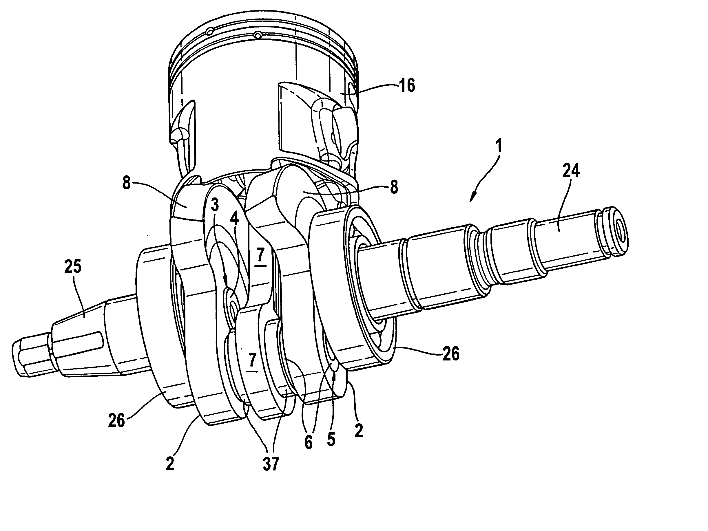
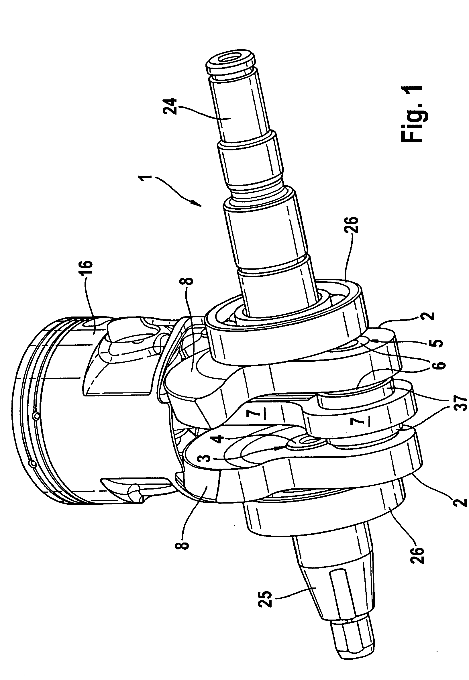
[0031]FIG. 1 shows a perspective view of details of an internal combustion engine for a portable handheld work apparatus. For the sake of clarity, only the region of the crankshaft 1 with a piston 16 and a connecting rod 7 is shown.

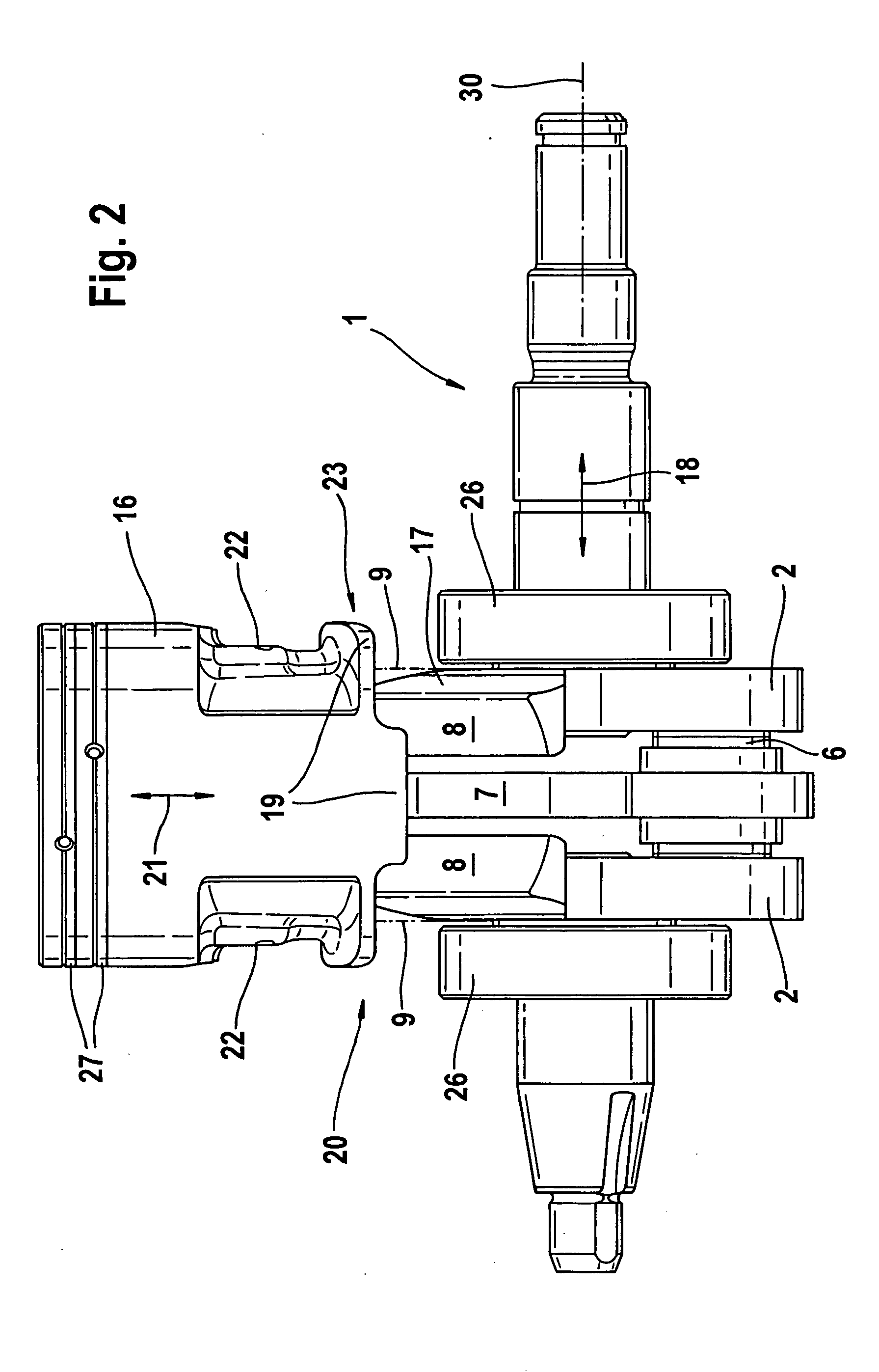
[0032] The crankshaft 1 is assembled from separately manufactured parts and includes two shaft sections (24, 25) as well as two crank arms 2 bordering on the shaft sections (24, 25). The two crank arms 2 are arranged symmetrically opposite each other and each has a central cutout 3 as well as an eccentric cutout 5. A shaft lug 4 is provided on the mutually adjacent ends of the two shaft sections (24, 25). With the shaft lugs 4, each of the shaft sections (24, 25) is connected in the central cutout 3 of the corresponding crank arm 2 so as to rotate therewith. A crank pin 6 runs through the eccentric cutouts 5 of the two crank arms 2. The connecting rod 7 is journalled on the crank pin 6 by means of a connecting rod bearing 37. At its opposite-lying end, t...


PUM


Abstract

The invention is directed to a crankshaft (1) of an internal combustion engine including an internal combustion engine for a portable handheld work apparatus such as a motor-driven chain saw or the like. The invention is also directed to a method for making the crankshaft (1) as well as an internal combustion engine with a corresponding crankshaft (1). The crankshaft (1) is made up of separately manufactured parts and includes a crank arm (2) having a central cutout (3) for accommodating a shaft lug (4) of the crankshaft (1) and an eccentric cutout (5) for accommodating a crank pin (6). The crank pin (6) journals a connecting rod (7). A centrifugal mass portion (8) is provided on the crank arm (2) at its end lying opposite the eccentric cutout (5). The centrifugal mass portion (8) is configured as one piece with the crank arm (2) and is bent out of a plane (9) of the crank arm (2) in the direction of the connecting rod (7).

Description

CROSS REFERENCE TO RELATED APPLICATION [0001] This application claims priority of German patent application No. 10 2004 013 870.2, filed Mar. 20, 2004, the entire content of which is incorporated herein by reference. FIELD OF THE INVENTION [0002] The invention relates to a crankshaft of an internal combustion engine and especially to the crankshaft of an internal combustion engine for a portable handheld work apparatus. The invention also relates to a method for making a crankshaft and to an internal combustion engine equipped with the crankshaft. BACKGROUND OF THE INVENTION [0003] Portable handheld work apparatus such as motor-driven chain saws, brushcutters, suction / blower apparatus or the like must be configured to be light and easily manipulable in order that they can be easily carried and guided. It is intended that an internal combustion engine as a drive motor should, referred to a pregiven piston displacement, exhibit high drive power and a low structural volume with low wei...

Claims


Application Information

Patent Timeline
Patent Type & Authority Applications(United States)
IPC IPC(8): B27B17/00F16C3/08F16C3/10
CPCF16C3/10B27B17/00
Inventor SCHMIDT, ROLANDGEYER, WERNER
Owner ANDREAS STIHL AG & CO KG
Why Eureka
Try Eureka