Eureka AIR delivers breakthrough ideas for toughest innovation challenges, trusted by R&D personnel around the world.

Escalator

a technology of escalators and escalators, which is applied in the direction of escalators, conveyers, transportation and packaging, etc., can solve the problem of only minimal load of wheels, and achieve the effect of reducing the structural space required and increasing the pitch

Inactive Publication Date: 2012-10-16
KETTEN WULF BETRIEBS GMBH & CO KG
View PDF23 Cites 7 Cited by
  • Summary
  • Abstract
  • Description
  • Claims
  • Application Information

AI Technical Summary

Benefits of technology

[0017]The effective lever arm of the chain at the at least one chain wheel in the upper strand is essentially equal to the effective lever arm of the chain at the at least one chain wheel in the lower strand. In the polygonal compensation configured for the upper strand, for example, this results not only in a constant velocity of the running of the upper strand, but also of the lower strand. The solution according to the present invention allows step or pallet chains with substantially increased pitch, such as chain pitch equal to half of the step pitch or a chain pitch equal to the step pitch, to be used and / or to reduce the structural space required.
[0018]In one example the first chain wheel and the second chain wheel are operated in a manner offset with respect to each other in such a way that, with a minimal effective lever arm at the first chain wheel in the same strand, the effective lever arm on the second chain wheel is not minimal, preferably deviates by ±20% or less of the difference between the maximum and minimum values from the maximum value, and is maximal, in particular. For this purpose, for example, the angular position of the first chain wheel can differ from that of the second chain wheel by at least ±30%, preferably by at least ±40% of the angular pitch, in particular by half of the angular pitch. This opposition in phase of the two chain wheels results in a reciprocating movement of the second chain wheel, configured as an idler wheel, for example, being reduced.
[0019]In one example the escalator has at least one guide, which can influence the entry angle of the chain on the first and / or the second chain wheel, wherein the at least one guide is arranged in such a way that the entry angle with the minimum effective lever arm is smaller than with the maximum effective lever arm. Such an arrangement of the guide has the result that the oscillating movement of the redirecting station approaches zero when the machine is running, which has a positive effect on running smoothness. Moreover, this arrangement of the at least one guide has the effect that the wheels are only minimally loaded. This means that it is possible to use relatively cheap wheels.

Problems solved by technology

Moreover, this arrangement of the at least one guide has the effect that the wheels are only minimally loaded.

Method used


Image

  • Escalator
  • Escalator
  • Escalator

Examples


first embodiment

[0027]I.1. The link chain drive which forms the basis of a first aspect of the invention comprises a drive chain sprocket for a link chain and comprises a drive system which can drive the drive chain sprocket with a non-uniform rotational speed for the purpose of compensating speed fluctuations of the link chain. Here and below, a “drive system” should be understood in a broad sense to mean any system which can output forces or torques to the drive chain sprocket. This encompasses in particular drive systems in the narrower sense, in which said forces or torques are actively generated, for example by means of an electric motor. Also encompassed, however, are “passive” drive systems in which said forces or torques are extracted from inertial systems such as for example a rotating flywheel mass. In a first embodiment, the link chain drive is characterized in that the drive system comprises the following elements:[0028]two wheels which are coupled by means of an endlessly encircling fl...

second embodiment

[0030]I.2. The invention furthermore relates to a link chain drive comprising a drive chain sprocket for a link chain and comprising a drive system (in the broad sense explained above) which can drive the drive chain sprocket with a non-uniform rotational speed for the purpose of compensating speed fluctuations of the link chain. Here, the drive system comprises two wheels which are coupled by means of an endlessly encircling flexible traction mechanism. According to a first variant, the link chain drive is characterized in that the axle of one of the two wheels is mounted eccentrically. According to a second variant, the link chain drive is characterized in that the axle of one of the two wheels is mounted so as to be movable and is connected to a diverting mechanism.

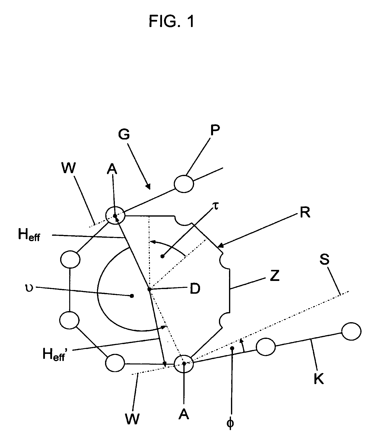
[0031]The eccentric mounting of the wheel causes a periodic change in length of the load-bearing strand, and as a result a non-uniform rotational speed of the drive chain sprocket, which reduces the polygon effect if t...

third embodiment

[0032]I.3. According to the underlying link chain drive having a drive chain sprocket for a link chain and having a drive system of non-uniform rotational speed, the drive system comprises the following elements:[0033]a motor, in particular an electric motor (geared motor), the rotor (component which is set in rotation) of which is coupled to the drive chain sprocket and the stator (component which does not rotate) of which is movable;[0034]a mechanism for moving the stator synchronously with the rotation of the drive chain sprocket.

[0035]Here, the stated mechanism preferably comprises a cam element which is coupled to and interacts with the drive chain sprocket and which is followed by a follower element, wherein the relative movement generated between the cam element and the follower element is transmitted to the stator of the motor.

[0036]II.1. According to a second aspect, the invention relates to a link chain drive which may be in particular an intermediate drive for an extended...


PUM


Abstract

An escalator includes a plurality of steps or panels, a chain for driving the steps or panels, at least one chain wheel around which the chain is deflected and wherein the chain, starting from the chain wheel, forms an upper strand and a lower strand. There is also provided a device for the polygonal compensation of the movement of the at least one chain wheel. The effective lever arm of the chain on the at least one chain wheel in the upper strand is substantially equal to the effective lever arm of the chain on the at least one chain wheel in the lower strand.

Description

BACKGROUND OF THE INVENTIONField of the Invention[0001]The present invention relates to an escalator.Definitions[0002]The term escalator should comprise both escalators with steps, as they are used in department stores, for example, and moving sidewalks with pallets, as they are used in airports, for example.[0003]FIG. 1 schematically shows a pintle chain G and a chain wheel R partially wrapped round the latter, to initially define a few terms. The pintle chain G comprises chain links K linked to each other via a pivot point P. The chain wheel K shown in an exemplary manner, has eight teeth Z, between which tooth spaces are arranged, into which pivot points P can engage. The angular pitch τ between two teeth or two tooth spaces is 45° in the example shown.[0004]Furthermore, an entry angle φ is shown at the bottom side of the chain wheel in FIG. 1, which can arise, for example, due to a guide for deflecting pintle chain G. The entry angle φ is measured between the actual exit directi...

Claims


Application Information

Patent Timeline
Patent Type & Authority Patents(United States)
IPC IPC(8): B65G21/00
CPCB66B23/026B66B23/022
Inventor GROBBEL, BURKHARD
Owner KETTEN WULF BETRIEBS GMBH & CO KG
Why Eureka
Eureka Blog
Learn More