High-pressure fuel pump with a pressure relief valve

a high-pressure fuel pump and pressure relief valve technology, which is applied in the direction of fuel injecting pumps, functional valve types, machines/engines, etc., can solve the problems of reducing the volumetric efficiency of high-pressure fuel pumps, and achieve the effect of reducing the number of high-pressure sealing points and cost saving

Active Publication Date: 2005-09-22
ROBERT BOSCH GMBH
View PDF8 Cites 56 Cited by
  • Summary
  • Abstract
  • Description
  • Claims
  • Application Information

AI Technical Summary

Benefits of technology

[0006] It is possible to integrate the pressure relief valve into the housing of the high-pressure fuel pump, without an additional high-pressure sealing point in the high-pressure region of the high-pressure fuel pump. This achieves significant cost savings and also reduces the number of high-pressure sealing points since a check valve is already provided between the

Problems solved by technology

The advantage of this high-pressure fuel pump is that the pressure relief valve does not open during the delivery stroke and consequently, transient pre

Method used


Image

  • High-pressure fuel pump with a pressure relief valve
  • High-pressure fuel pump with a pressure relief valve
  • High-pressure fuel pump with a pressure relief valve

Examples


Embodiment Construction

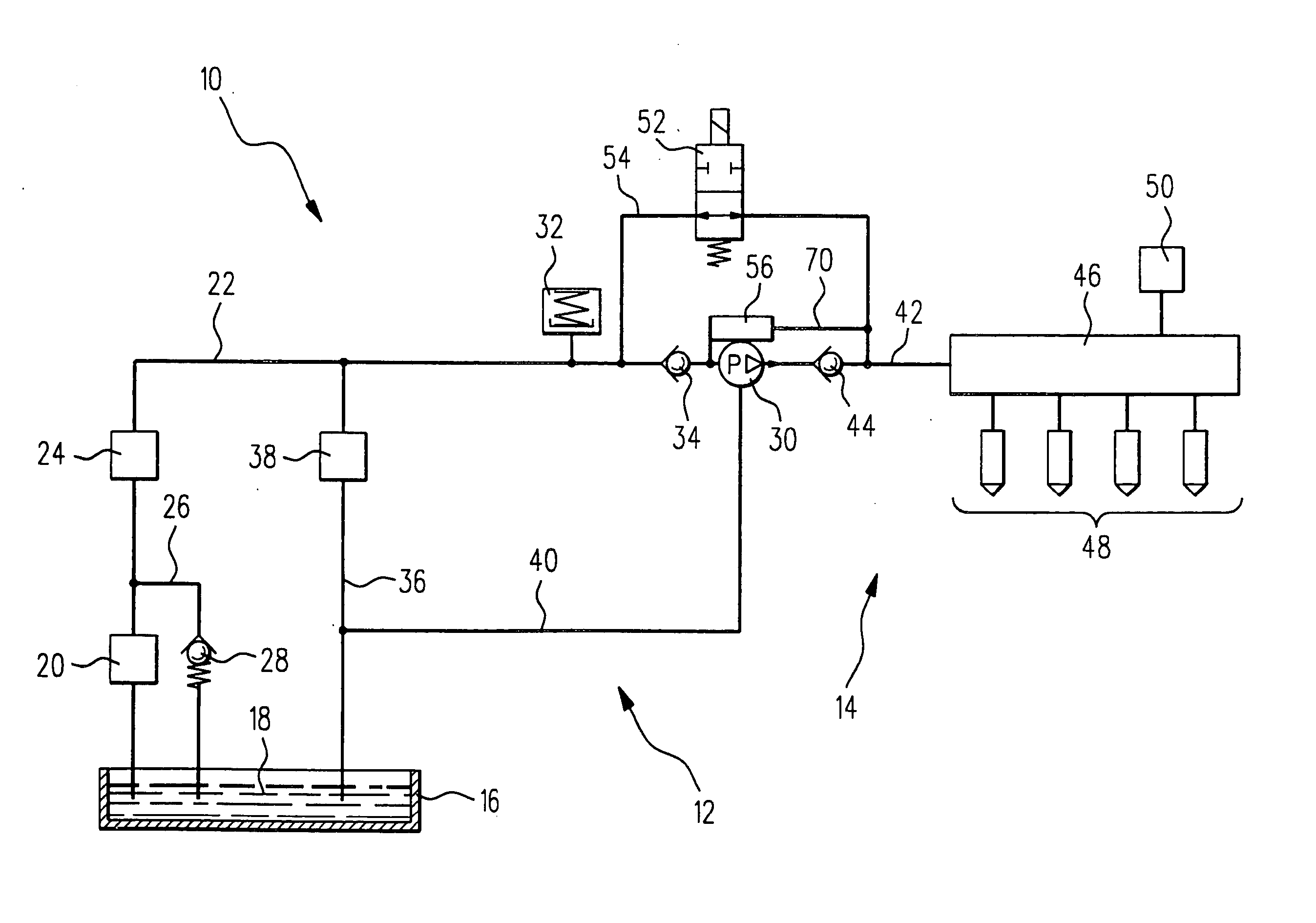
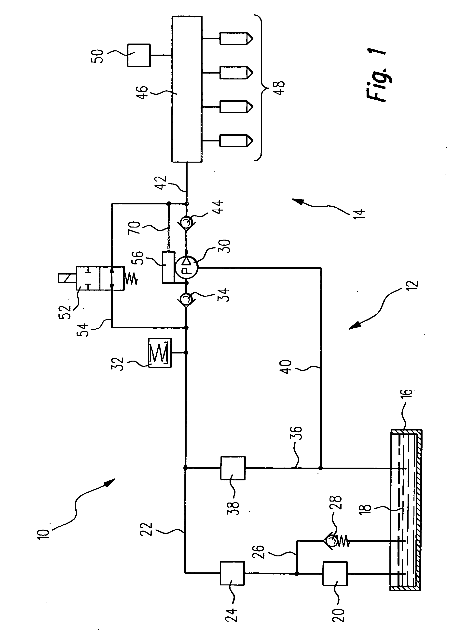
[0022] In FIG. 1, a fuel system is labeled as a whole with reference numeral 10, and includes a low-pressure region 12 and a high-pressure region 14. The low-pressure region 12 includes a tank 16 in which fuel 18 is stored. The fuel 18 is fed from the tank 16 by a first fuel pump 20, which is an electric fuel pump. The electric fuel pump 20 feeds into a low-pressure fuel line 22 provided with a filter 24 downstream of the electric fuel pump 20. Upstream of the filter 24, a first branch line 26 branches off from the low-pressure fuel line 22 and leads back to the tank 16. The first branch line 26 contains a pressure relief device 28.

[0023] The low-pressure line 22 leads to a high-pressure pump 30, which is driven in a manner not shown here by the camshaft of an internal combustion engine, not shown. The high-pressure pump 30 is a one-piston high-pressure pump. Upstream of the high-pressure pump 30 a pressure damper 32 and an intake valve 34 are also provided in the low-pressure fuel...


PUM


Abstract

A high-pressure fuel pump with a pressure relief valve which has improved hydraulic properties and a reduced number of high-pressure sealing points.

Description

BACKGROUND OF THE INVENTION [0001] 1. Field of the Invention [0002] The invention relates to a high-pressure fuel pump with a delivery chamber that is connected on the intake side via an intake valve to a low-pressure fuel line and is connected on the pressure side via a high-pressure connection to a high-pressure fuel line, in which a check valve and a pressure relief valve connected parallel to it are provided between the delivery chamber contained in a housing and the high-pressure connection connected in a fluid-tight manner to the housing, and the pressure relief valve is contained in a blind hole bore of the housing. [0003] 2. Description of the Prior Art [0004] A high-pressure fuel pump of the type with which this invention is concerned is known from DE 103 27 411, which was published after the priority date of the present application. The advantage of this high-pressure fuel pump is that the pressure relief valve does not open during the delivery stroke and consequently, tra...

Claims


Application Information

Patent Timeline
IPC IPC(8): F02M1/00F02M59/46F02M63/02F16K17/04
CPCF02M63/0036F02M63/005F16K17/0406F02M63/0225F02M63/0054F02M59/46
Inventor REMBOLD, HELMUTROPERTZ, PETERTOSCANO, VICTORIO
Owner ROBERT BOSCH GMBH
Why Eureka
Try Eureka