Desoldering sheath

a technology of desoldering sheaths and sheaths, which is applied in the direction of soldering apparatus, manufacturing tools,auxillary welding devices, etc., can solve the problems of users who have a difficult time holding the vacuum pump or the solder wick in intimate contact, and the conventional methods of removing solder, vacuum pump methods and solder wick methods are two-handed operations

Inactive Publication Date: 2005-09-22
CHOI MOON GUL +1
View PDF13 Cites 12 Cited by
  • Summary
  • Abstract
  • Description
  • Claims
  • Application Information

AI Technical Summary

Problems solved by technology

The use of these conventional methods for removing solder has its drawbacks.
One important drawback is that both the vacuum pump method and the solder wick method are two-handed operations.
This presents problems for some users who have a difficult time holding the vacuum pump or solder wick in intimate contact with the solder as the solder is being heated by the desoldering gun.
Another drawback of the vacuum pump is that the solder will harden within the vacuum pump after it has been removed from the PCB.
It then becomes a tedious task to remove the hardened solder from the vacuum pump.

Method used


Image

  • Desoldering sheath
  • Desoldering sheath
  • Desoldering sheath

Examples


Embodiment Construction

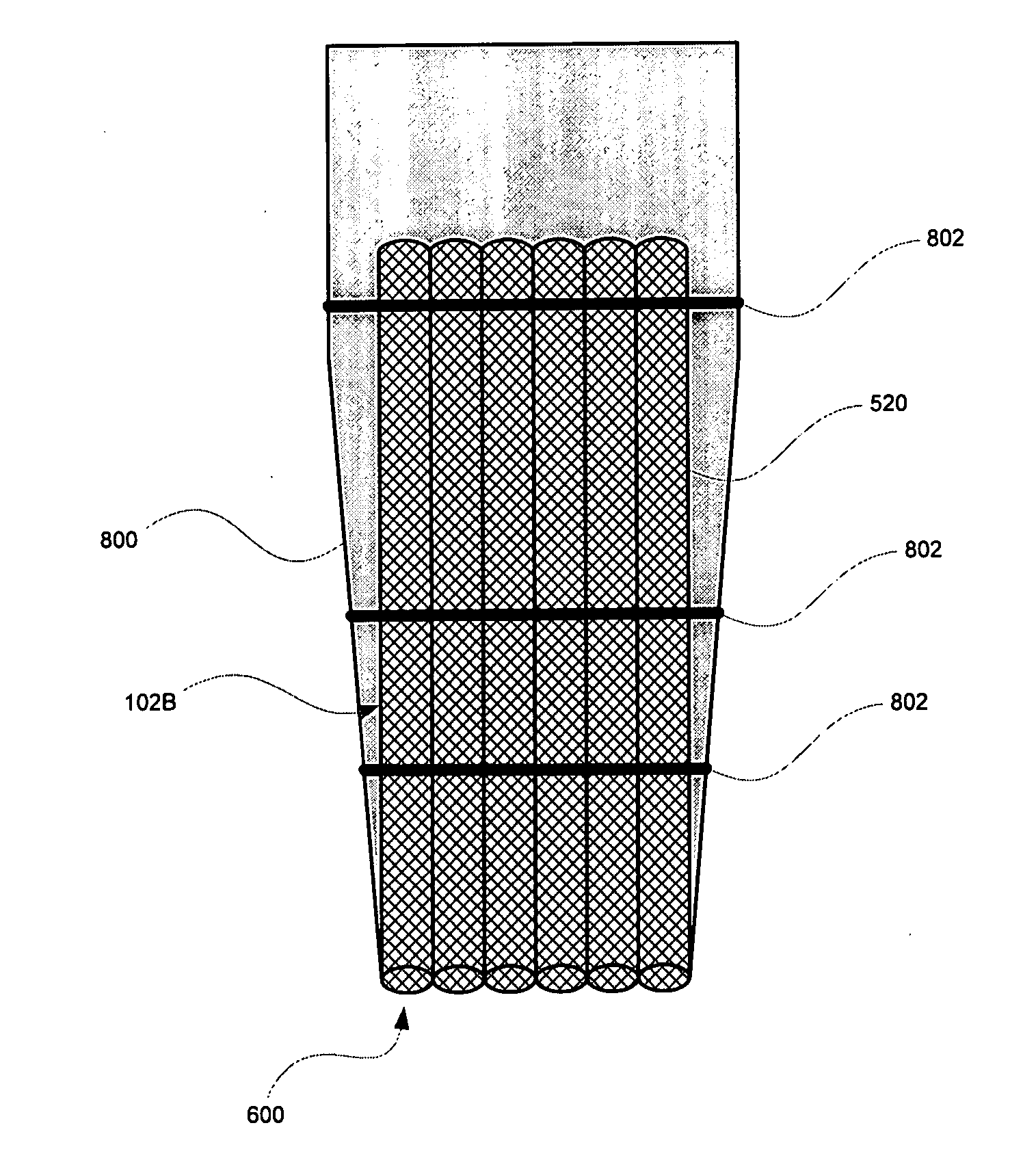
[0024] The invention is a desoldering sheath that can be used in conjunction with a desoldering gun (or a desoldering iron) to remove solder from a printed circuit board. The desoldering sheath is configured to be placed directly over the tip of the desoldering gun, covering the tip substantially in its entirety. This enables a user to perform one-handed desoldering operations.

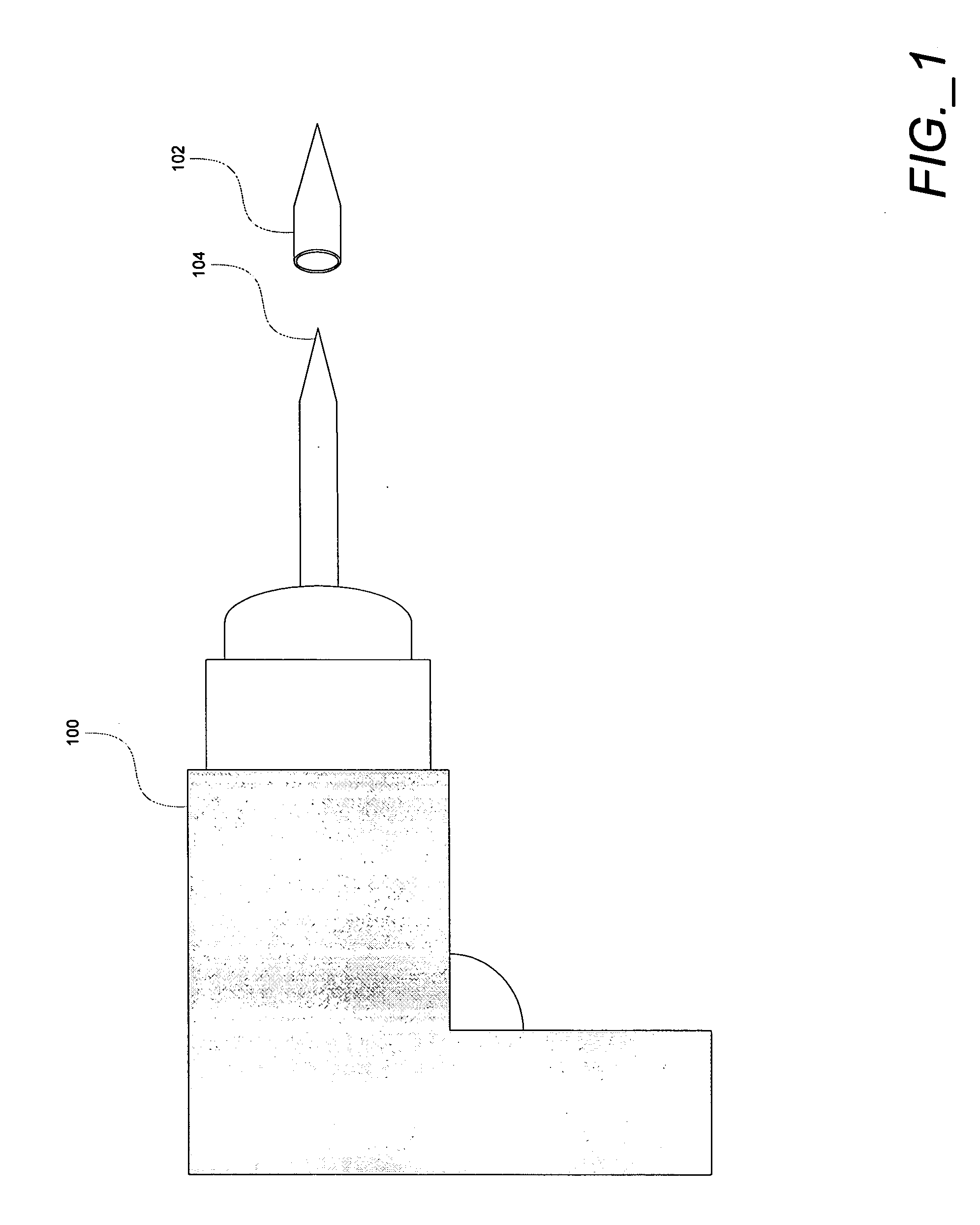
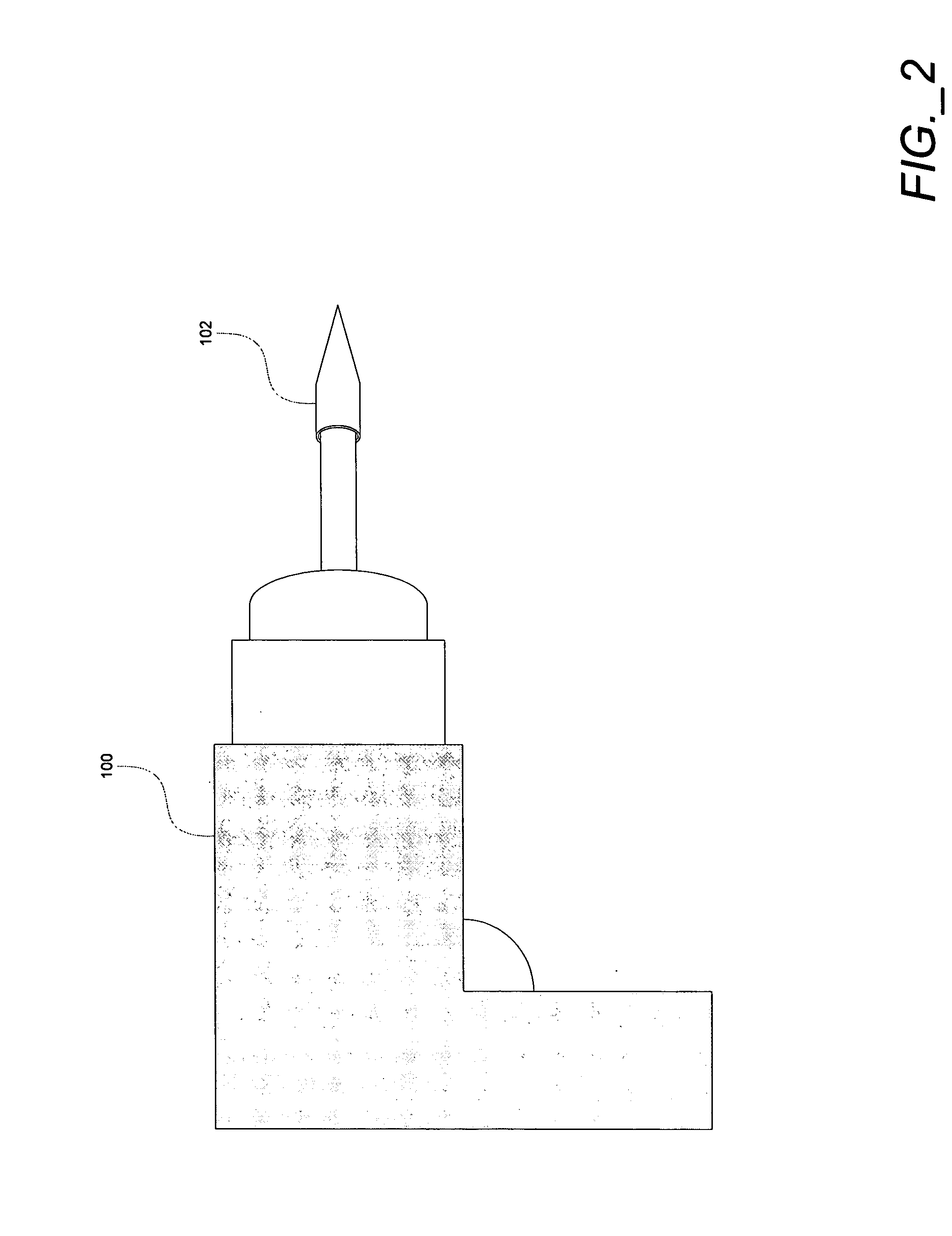
[0025]FIG. 1 illustrates a desoldering gun 100 and one implementation of a desoldering sheath 102 according to the invention. The desoldering gun 100 includes a cone-shaped tip 104 through which heat can be transmitted. During a conventional desoldering operation, the tip 104 is heated and placed into contact with solid solder that needs to be removed. The heat from the tip 104 is transmitted to the solder causing it to melt. The molten solder is then captured using a solder wick (also known as a desoldering braid). The solder wick is placed into contact with the melted solder, and is often placed in between ...


PUM

PropertyMeasurementUnit
diameteraaaaaaaaaa
adhesiveaaaaaaaaaa
diameteraaaaaaaaaa

Abstract

A desoldering sheath that comprises at least one hollow metal wire molded to conform to the tip of a desoldering tool. In one implementation, the desoldering sheath is formed using a hollow metal wire that is coiled around a male cone-shaped mold. The coiled, hollow metal wire is then compressed between the male cone-shaped mold and a female cone-shaped mold to cause the hollow wire to retain the coiled shape. In use, the desoldering sheath is placed on the tip of a desoldering gun or iron and then heated. The heated desoldering sheath, while still on the tip of the desoldering gun or iron, is then placed into contact with solder. This causes the solder to melt and the desoldering sheath captures the molten solder by using capillary action to draw the molten solder into the hollow metal wire.

Description

FIELD OF THE INVENTION [0001] The invention relates to desoldering equipment, namely a desoldering sheath for use with a desoldering gun or iron. BACKGROUND OF THE INVENTION [0002] Desoldering is a process for removing solder from a printed circuit board (PCB). Known methods for desoldering require two pieces of equipment, a desoldering gun (or a desoldering iron) and a device to remove the solder affixed to the PCB. The desoldering gun serves as a heat source for the desoldering operation. The desoldering gun includes a metal tip that is used to transfer heat to both the solder and the device used to remove the solder. The tip of the desoldering gun generally has either a tapered shape (i.e., conical or pointed) or a square shape. [0003] Conventional devices to remove solder include vacuum pumps and solder wicks. A vacuum pump, also known as a solder sucker, is a suction device resembling a large syringe. The vacuum pump includes a spring loaded plunger to create suction. The plung...

Claims


Application Information

Patent Timeline
Patent Type & Authority Applications(United States)
IPC IPC(8): B23K1/00B23K1/018B23K3/00B23K3/08B23K31/00
CPCB23K3/026B23K1/018B23K3/08B23K37/00B23K2101/42
Inventor CHOI, MOON GULCHOI, CRISWELL HYUNSOO
Owner CHOI MOON GUL
Why Eureka
Try Eureka