Diaphragm and hydraulically-operated valve using same

a hydraulically operated valve and diaphragm technology, applied in the direction of diaphragm valves, engine diaphragms, machines/engines, etc., can solve the problems of inoperable valves, large valves of 8′′ or more, and failure of diaphragms, so as to achieve reliable closing and long operating life

Inactive Publication Date: 2005-09-22
RAPHAEL VALVES INDS 1975
View PDF3 Cites 53 Cited by
  • Summary
  • Abstract
  • Description
  • Claims
  • Application Information

AI Technical Summary

Benefits of technology

[0013] It is therefore one of the objects of the present invention to obviate the disadvantages of prior art diaphragms and to provide a hydraulical

Problems solved by technology

Large valves, about 8″ or more, are more difficult to operate, particularly when the fluid being transported is at high pressure, because the forces needed to prevent flow increase as the square of the pipeline diameter.
The cost of a failed diaphragm goes far beyond the cost of a replacement, as leakage needs to be controlled, a technician needs to be sent to the site and the pipeline may need to be shut down during replacement of the failed component.
The problem with this design is that at small pressure differences and low flow rates the metallic spring causes vibrations which quickly damage the diaphragm, thus making the valve inoper

Method used


Image

  • Diaphragm and hydraulically-operated valve using same
  • Diaphragm and hydraulically-operated valve using same
  • Diaphragm and hydraulically-operated valve using same

Examples


Embodiment Construction

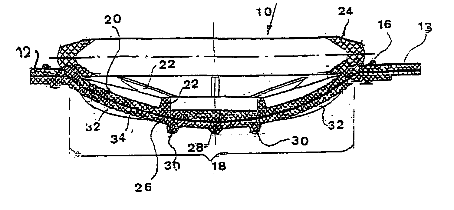
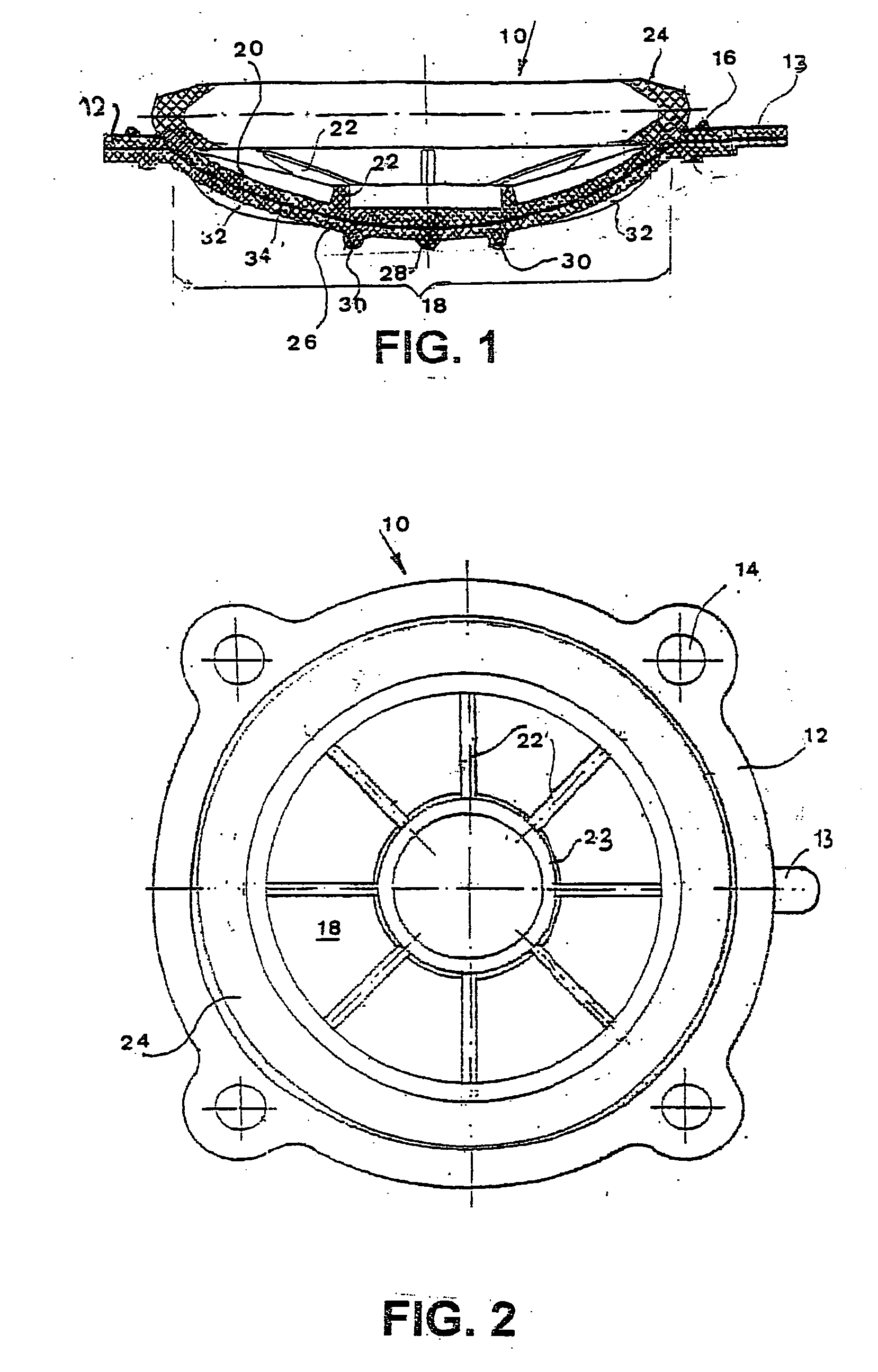
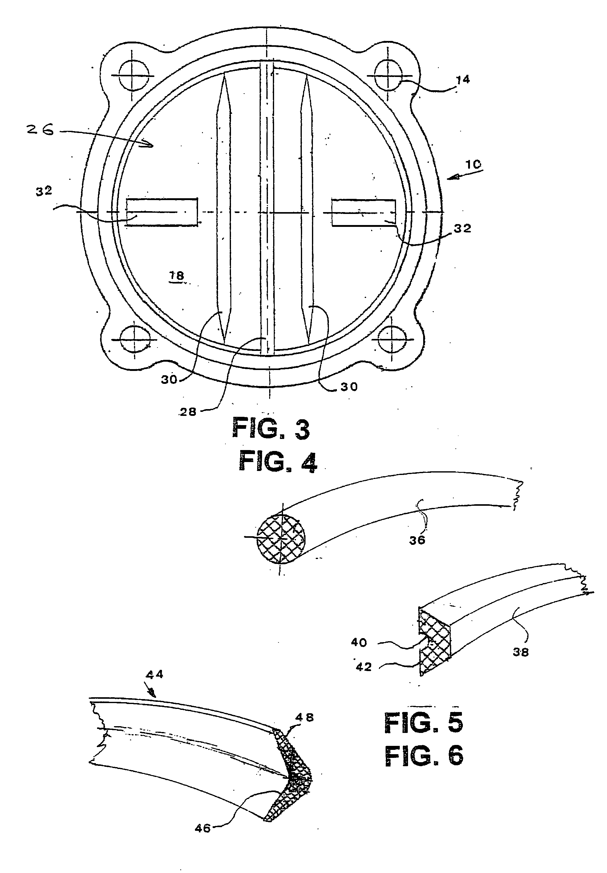
[0034] There is seen in FIGS. 1, 2 and 3 an elastomer diaphragm 10 for use in a hydraulically-operated valve (seen in FIG. 7) and in a hydraulic pressure regulator (not shown).

[0035] The material to be used for manufacturing the diaphragm is dependent on the type of fluid being carried and on the temperature range to which the diaphragm is to be exposed. Typical suitable materials are Nitrile butadiene rubber and Neoprene.

[0036] The diaphragm 10 has an outer, substantially flat area 12 allowing clamping by the valve (seen in FIG. 2) an orientation tab 13 and multiple apertures 14 for passage of fasteners (not seen). Area 12 is provided with sealing beads 16, as known in the prior art. (U.S. Pat. No. 2,302,930 to Anderson).

[0037] The central portion 18 of the diaphragm 10 is bulged to avoid excessive stretching of the diaphragm material when in use, and to enhance stability in both upper and lower positions.

[0038] An upper face 20 is arranged to be exposed to a control hydraulic ...


PUM


Abstract

The present invention relates to fluid control valves. The invention provides an improved diaphragm useful for a large hydraulically-operated valve or pressure regulating valve of the type used in pipelines to transport water, oil, gas, acids, alkalis and other fluids. The diaphragm being provided with an upper face arranged to be exposed to a control hydraulic pressure and a lower face arranged to selectively seal and open a passage between a valve inlet and a valve outlet, ribs on said upper face urging the diaphragm towards a sealing position. The diaphragm being characterized by the addition of an elastomer ring element disposed adjacent to the upper face and adjacent to the largest diameter of the diaphragm exposed inside a valve to which it may be assembled, an upper face of the flexible ring element being in pressure contact with a portion of the rigid body of the valve. The flexible ring element further urging the diaphragm towards its lower position and allowing closure of the valve without use of a metallic compression spring.

Description

CROSS-REFERENCE [0001] This application claims priority of Israel Patent Applications, 156797, filed Jul. 6, 2003. BACKGROUND OF THE INVENTION [0002] The present invention relates to fluid control valves. [0003] More particularly, the invention provides an improved diaphragm useful for a large hydraulically-operated valve or pressure regulating valve of the type used in pipelines to transport water, oil, gas, acids, alkalis and other fluids. [0004] Although valves can be installed and operated in any position, in the present specification the term lower refers to the side of the diaphragm always in contact with the fluid being transported. Upper refers to the opposite side of the diaphragm which may be in contact with a fluid to control opening / closing of the valve. [0005] Small fluid control valves are easily actuated by hand, foot, machine, solenoid or pilot air. Large valves, about 8″ or more, are more difficult to operate, particularly when the fluid being transported is at high...

Claims


Application Information

Patent Timeline
IPC IPC(8): F16KF16K7/12F16K31/145
CPCF16K31/145F16K7/126
Inventor FRENKEL, BORIS
Owner RAPHAEL VALVES INDS 1975
Why Eureka
Try Eureka