Power generation system and control method

a power generation system and control method technology, applied in the direction of electric generator control, emergency power supply arrangement, turbine/propulsion engine ignition, etc., can solve the problems of high system cost, long time to supply enough electric power to the load, and unit micro gas turbine system cannot be quickly restarted, so as to simplify the structure of the power generation system and reduce the cost of the system

Inactive Publication Date: 2005-09-22
HITACHI LTD
View PDF5 Cites 24 Cited by
  • Summary
  • Abstract
  • Description
  • Claims
  • Application Information

AI Technical Summary

Benefits of technology

[0009] By the present invention, the whole power generation system can be started up by providing a storage battery to only one unit power generation system, without the need of equipp

Problems solved by technology

However, each unit power generation system has to be equipped with a storage battery and that drives up the cost of the whole system.
Further, the above technique once stops the unit micro gas turbine systems when the operation mode of the micro gas turbine system is switched to stand-alone operation due to the outage of power system.
Thus, the unit micro gas turbine systems can not be restarted

Method used


Image

  • Power generation system and control method
  • Power generation system and control method
  • Power generation system and control method

Examples


embodiment 1

[0025] In the following, a first embodiment in accordance with the present invention will be described referring to FIGS. 1 through 3. While the following explanation will be given mainly taking a gas turbine power generation system as an example, the embodiment is also applicable to various power generation systems that make preparations for power generation by use of auxiliary machinery power sources like engine generators, fuel cell systems, etc.

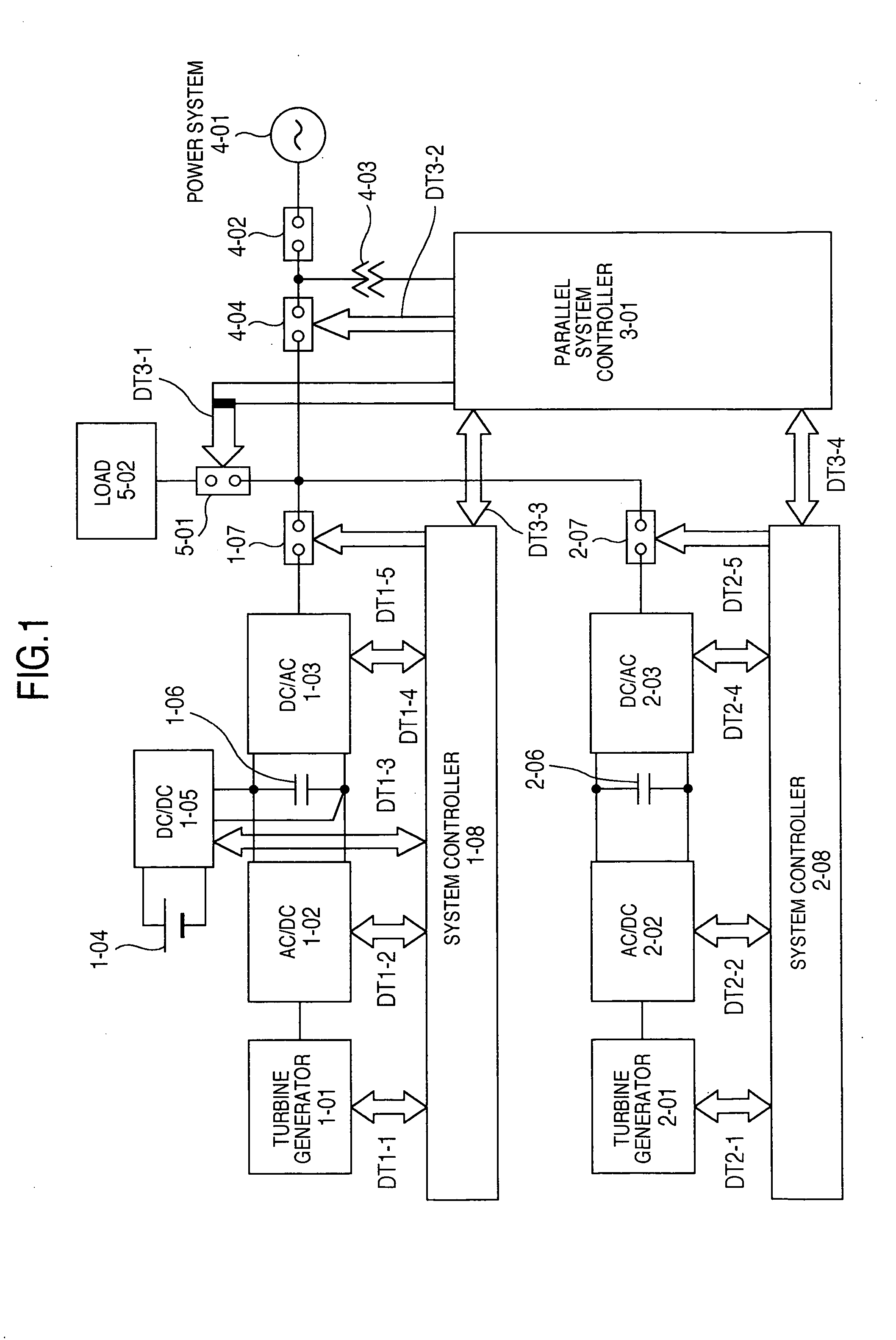
[0026]FIG. 1 is a block diagram showing a gas turbine power generation system in accordance with the first embodiment of the present invention. First, the composition and basic operation of the system will be explained referring to FIG. 1. The gas turbine power generation system has a parallel connection structure, in which a plurality of (two in FIG. 1) systems are connected in parallel at the output end.

[0027] Although not shown in FIG. 1, each system mainly comprises a turbine generator 1-01, 2-01 (including a combustion chamber, a t...

embodiment 2

[0113] In the following, another embodiment in accordance with the present invention will be described referring to FIGS. 5 and 6, wherein like reference characters designate like or corresponding parts throughout the views and thus repeated description thereof is omitted for brevity.

[0114] In order to supply electric power to the load even when the power system 4-01 can not supply power to the gas turbine power generation system due to abnormality like power outage (periods P2-P4), it is possible to cut the gas turbine power generation system and the load away from the power system 4-01 so as to let the gas turbine power generation system supply power to the load and thereafter connect the gas turbine power generation system and the load to the power system 4-01 when its abnormality has been eliminated.

[0115] A method for supplying electric power to the load in case of outage of the power system 4-01 will be described with reference to FIGS. 5 and 6. First, the operation of the g...


PUM


Abstract

A power generation system includes a first unit power generation system having a storage battery, a second unit power generation system having no storage battery and a controller, at a time of starting up of the power generation system, the controller first starts up the first unit power generation system and then starts up the second unit power generation system having no storage battery by supplying electric power generated by the first unit power generation system to the second unit power generation system.

Description

BACKGROUND OF THE INVENTION [0001] The present invention relates to a power generation system capable of starting up in stand-alone operation and a control method for the power generation system. [0002] In a micro gas turbine system described in a document: Isamu Inoue “UPS Function Built-in Micro-turbine Power Generation System” Meiden Jiho 2002, No. 2, pages 14-17, a plurality of unit micro gas turbine systems are started up in stand-alone operation, independently of a power system for supplying electric power to the micro gas turbine system. [0003] For the stand-alone startup operation, each of the unit micro gas turbine systems is equipped with a power converter system including a storage battery. When power supply to the load is started after outage of the power system, the unit micro gas turbine systems are stopped once and then restarted. [0004] In the above technique allowing the micro gas turbine system start up in stand-alone operation independently of the power system, ea...

Claims


Application Information

Patent Timeline
IPC IPC(8): F02C6/00F01K13/02F02C7/26H02J7/00H02J9/08H02P9/04
CPCH02J9/08
Inventor ICHINOSE, MASAYAFUTAMI, MOTOONAKANO, SUSUMU
Owner HITACHI LTD
Why Eureka
Try Eureka