Current-perpendicular-to-plane magnetoresistive sensor with free layer stabilized by in-stact orthogonal magnetic coupling to an antiparallel pinned biasing layer

a magnetoresistive sensor and free layer technology, applied in the field of current perpendicular to the plane (cpp) magnetoresistive sensors, can solve the problems of undesirable additional bias on the free layer, general inability to use the structure incorporating it, etc., and achieve the effect of reducing the parasitic electrical resistance of the sensor

Active Publication Date: 2005-09-22
WESTERN DIGITAL TECH INC
View PDF13 Cites 25 Cited by
  • Summary
  • Abstract
  • Description
  • Claims
  • Application Information

AI Technical Summary

Problems solved by technology

However, because cobalt-ferrite is an electrical insulator, structures incorporating it are generally not usable in CPP sensors.
This case is magnetically similar to an antiferromagnetic spacer and will therefore also induce frustration leading to orthogonal coupling of the ferromagnetic layers.
When the in-stack biasing layer is a single ferromagnetic layer, like biasing layer 244 in FIG. 2, and is patterned to the TW dimension, magnetostatic coupling between the edges of the biasing and free layers may cause an undesirable additional bias on the free layer.

Method used


Image

  • Current-perpendicular-to-plane magnetoresistive sensor with free layer stabilized by in-stact orthogonal magnetic coupling to an antiparallel pinned biasing layer
  • Current-perpendicular-to-plane magnetoresistive sensor with free layer stabilized by in-stact orthogonal magnetic coupling to an antiparallel pinned biasing layer
  • Current-perpendicular-to-plane magnetoresistive sensor with free layer stabilized by in-stact orthogonal magnetic coupling to an antiparallel pinned biasing layer

Examples


Embodiment Construction

Prior Art

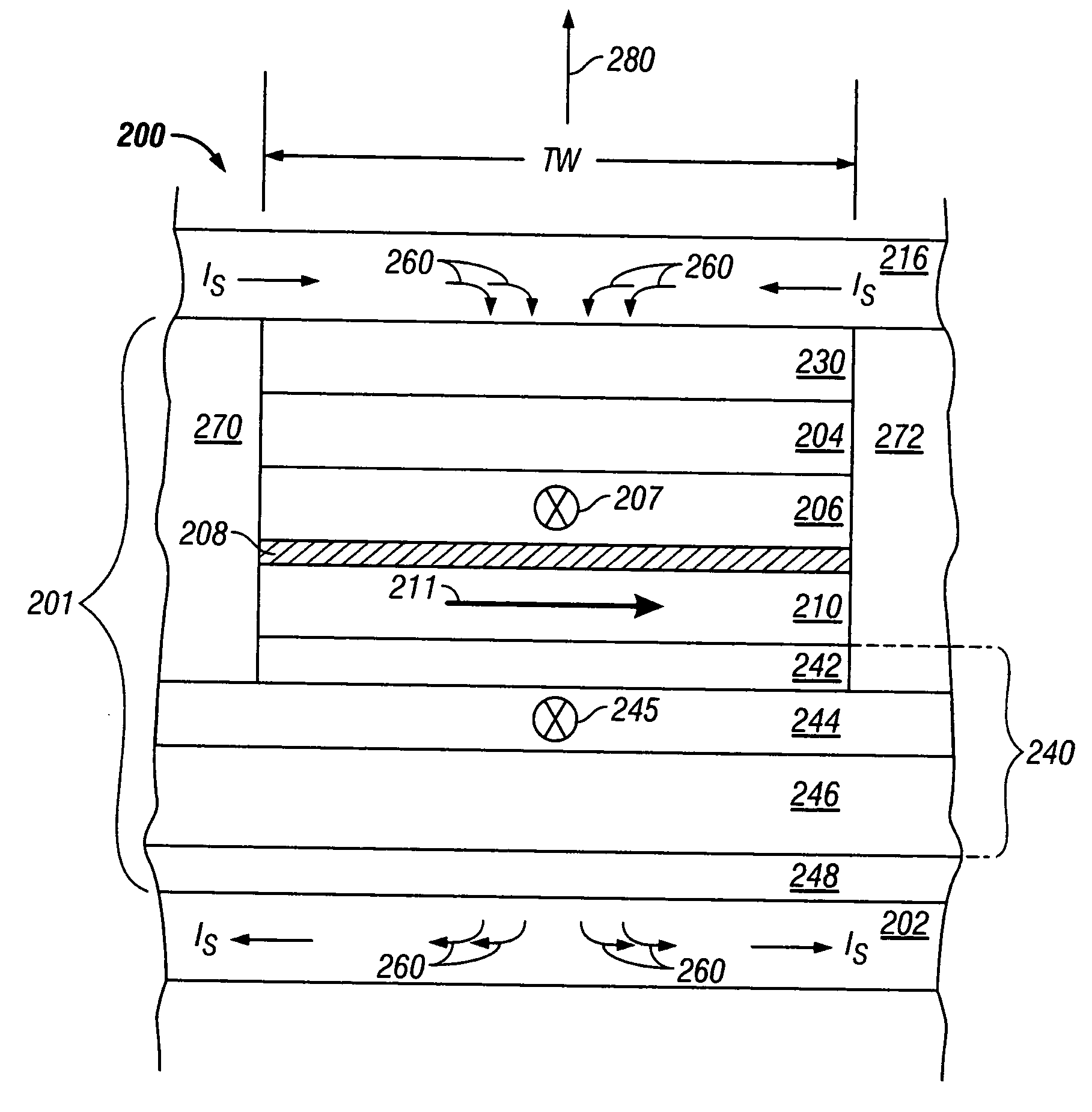
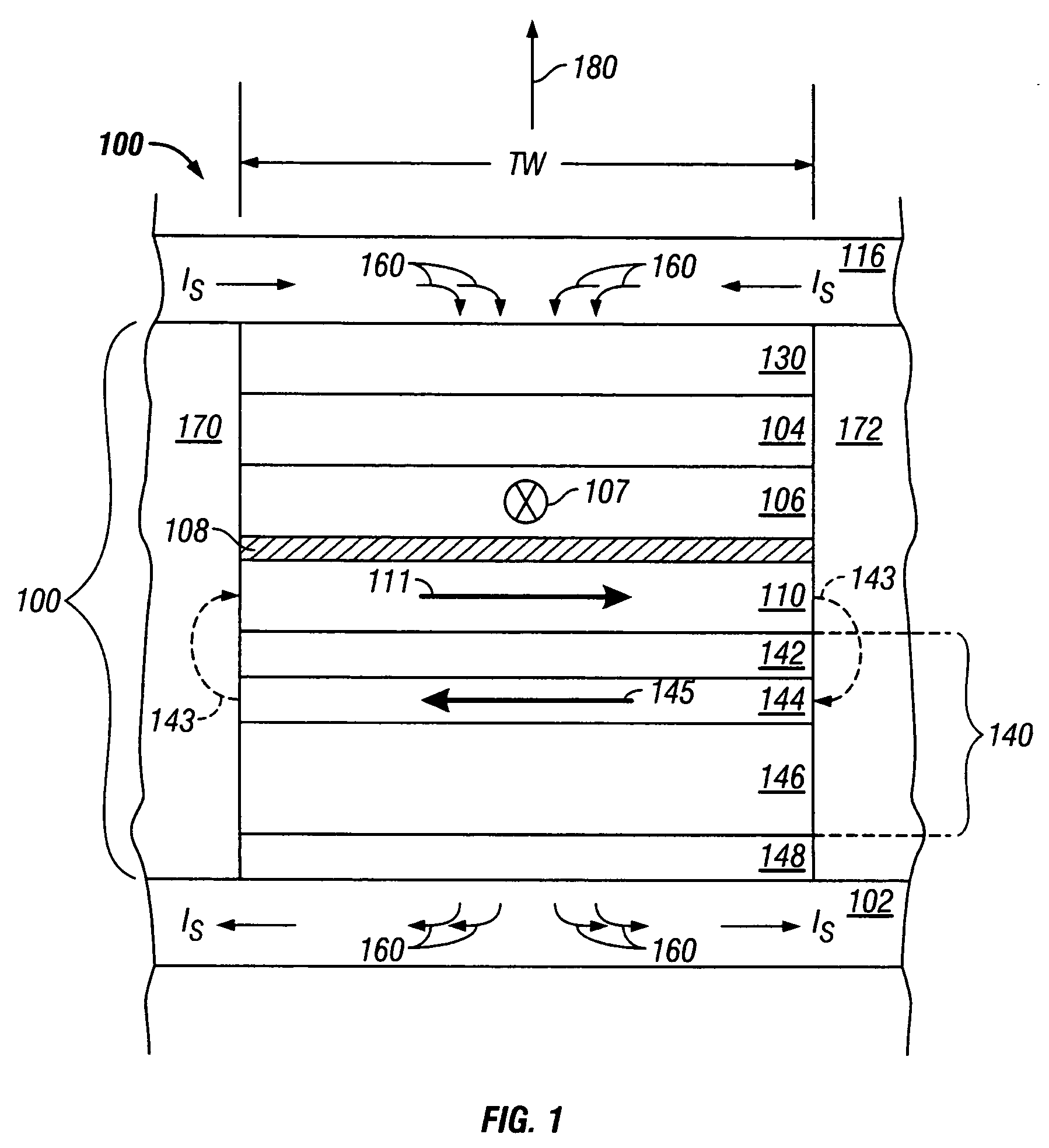
[0020]FIG. 1 is a sectional view of a prior art current-perpendicular-to-the-plane (CPP) sensor 100 with in-stack biasing and depicted as a disk drive magnetoresistive read head as it would appear when viewed from the disk. Sensor 100 comprises a stack 101 of layers formed on a substrate 102, which in the case of a read head is the bottom magnetic shield that also serves as the bottom electrical lead. A top magnetic shield 116 on stack 101 also serves as the top electrical lead. The sensor stack 101 is located in the gap between the generally planar surfaces of shields 102, 116. The gap material 170, 172 on the sides of the sensor stack 101 is an insulating material, typically an oxide such as alumina (Al2O3). Sense current Is flows perpendicularly through the layers in the stack 101 between the two leads / shields 116, 102, as shown by arrows 160. The width of the data tracks that can be resolved on the disk is determined by the trackwidth (TW) of the sensor stack 101. The...


PUM

PropertyMeasurementUnit
thicknessaaaaaaaaaa
thicknessaaaaaaaaaa
thicknessaaaaaaaaaa

Abstract

A magnetically-coupled structure has two ferromagnetic layers with their in-plane magnetization directions coupled orthogonally across an electrically-conducting spacer layer that induces the direct orthogonal magnetic coupling. The structure has application for in-stack biasing in a current-perpendicular-to-the-plane (CPP) magnetoresistive sensor. One of the ferromagnetic layers of the structure is an antiparallel-pinned biasing layer and the other ferromagnetic layer is the sensor free layer. The antiparallel-pinned biasing layer has first and second ferromagnetic films separated by an antiferromagnetically-coupling film. An antiferromagnetic layer exchange-couples the first ferromagnetic film of the biasing layer to fix the net moment of the biasing layer parallel to the moment of the sensor pinned layer. This allows a single annealing step to be used to set the magnetization direction of the biasing and pinned layers.

Description

RELATED APPLICATION [0001] This application is a continuation-in-part of pending application Ser. No. 10 / 802,639 filed Mar. 16, 2004 and titled “CURRENT-PERPENDICULAR-TO-PLANE MAGNETORESISTIVE SENSOR WITH FREE LAYER STABILIZED BY IN-STACK ORTHOGONAL MAGNETIC COUPLING”.TECHNICAL FIELD [0002] The invention relates to a current-perpendicular-to-the-plane (CPP) magnetoresistive sensor that operates with the sense current directed perpendicularly to the planes of the layers making up the sensor. BACKGROUND OF THE INVENTION [0003] One type of conventional magnetoresistive sensor, often called a “spin-valve” (SV) sensor, has a stack of layers that include two ferromagnetic layers separated by a nonmagnetic spacer layer. One ferromagnetic layer has its magnetization direction fixed, such as by being pinned by exchange coupling with an adjacent antiferromagnetic layer, and the other ferromagnetic layer has its magnetization direction “free” to rotate in the presence of an external magnetic f...

Claims


Application Information

Patent Timeline
Patent Type & Authority Applications(United States)
IPC IPC(8): G01R33/09G11B5/127G11B5/33G11B5/39H01F10/30H01F10/32
CPCB82Y10/00B82Y25/00H01F10/3295H01F10/30H01F10/3268G11B5/3903
Inventor CAREY, MATTHEW J.CHILDRESS, JEFFREY R.HO, KUOK SANMAAT, STEFAN
Owner WESTERN DIGITAL TECH INC
Why Eureka
Try Eureka