Optical discriminating apparatus, optical disc discriminating method, optical disc recording apparatus and optical disc reproducing apparatus

a technology of optical discs and discriminating devices, applied in the direction of digital signal error detection/correction, instruments, recording signal processing, etc., can solve the problems of inability to alert the user, recording and/or reproducing equipment is not possible,

Inactive Publication Date: 2005-09-22
SONY CORP
View PDF3 Cites 0 Cited by
  • Summary
  • Abstract
  • Description
  • Claims
  • Application Information

AI Technical Summary

Benefits of technology

[0014] It is an object of the present invention to provide an optical disc discriminating apparatus and an optical disc discriminating method whereby it is possible to discriminate the optical disc which has the outer shape and the optical system in common with the next generation MD1 but which is different in the UTOC recording system, such as the aforementioned next generation MD2. It is another object of the present invention to provide an optical disc recording apparatus and an optical disc reproducing apparatus for recording and reproducing the information, respectively, after discriminating the sort of the loaded optical disc by the above optical disc discriminating apparatus and method.

Problems solved by technology

Moreover, since there is provided no alerting area, it is impossible to alert to the user that the MD loaded is of such a sort that recording and / or reproduction is not possible with the recording and / or reproducing apparatus.

Method used


Image

  • Optical discriminating apparatus, optical disc discriminating method, optical disc recording apparatus and optical disc reproducing apparatus
  • Optical discriminating apparatus, optical disc discriminating method, optical disc recording apparatus and optical disc reproducing apparatus
  • Optical discriminating apparatus, optical disc discriminating method, optical disc recording apparatus and optical disc reproducing apparatus

Examples


Embodiment Construction

[0056] Referring to the drawings, a certain preferred embodiment of the present invention is explained in detail.

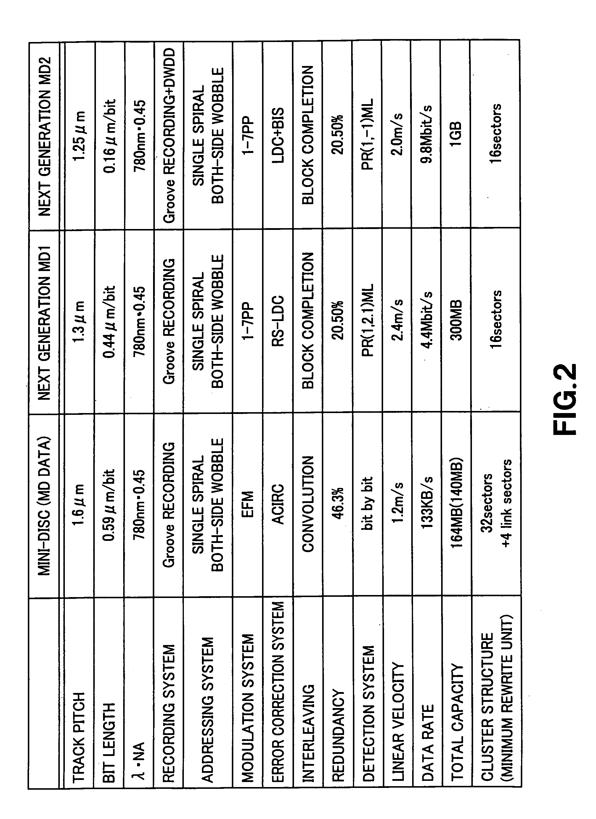
[0057] The preferred embodiment of the present invention is directed to a second magneto-optical disc, developed from the Mini-Disc (registered trademark) MD, and a third magneto-optical disc which is undistinguishable in outer shape from this second magneto-optical disc, as two sorts of disc-shaped magneto-optical discs, in which data is recorded in a wobbled groove or land, an address is indicated by the wobbled groove and in which the recording capacities differ even though the outer shape is the same. As will be explained subsequently, the third magneto-optical disc is larger in recording capacity than the second magneto-optical disc. That is, the optical disc discriminating apparatus of the present embodiment is designed for discriminating the two sorts of the magneto-optical discs of respective different recording capacities from each other. Although the disc-shape...


PUM

PropertyMeasurementUnit
diameteraaaaaaaaaa
lengthaaaaaaaaaa
linear velocityaaaaaaaaaa

Abstract

A tracking error signal calculating unit (221) detects a tracking error signal of light with respect to a mark recorded on a wobbled groove in a focused-on state from the light reflected back from the wobbled groove. A pull-in signal calculating unit (225) detects a total light volume signal PI of the mark, recorded on the wobbled groove, from the reflected light. A D-flipflop discriminating circuit (244) compares the phase of a binary coded version of a tracking error signal TE detected by the tracking error signal calculating unit to the phase of a binary coded version of the total light volume signal PI as detected by the pull-in signal calculating unit to discriminate the sorts of the optical discs having the same outer shape and the same optical system but differing in the UTOC recording system.

Description

CROSS REFERENCE TO RELATED APPLICATIONS [0001] This application is a continuation of U.S. application Ser. No. 10 / 478,212 filed Nov. 28, 2003, and further is based upon and claims the benefit of priority from the prior Japanese Patent Application No. 2002-098050, filed in Japan on Mar. 29, 2002, the entire contents of each of which are incorporated herein by reference.BACKGROUND OF THE INVENTION [0002] 1. Technical Field [0003] This invention relates to an optical disc discriminating apparatus and an optical disc discriminating method for discriminating plural different sorts of the optical discs which are the same in recording system, addressing system and outer shape but different in recording capacity. This invention also relates to an optical disc recording apparatus and an optical disc reproducing apparatus for recording the information and for reproducing the information, respectively, after discriminating the sort of an optical disc loaded in position thereon by the above-men...

Claims


Application Information

Patent Timeline
Patent Type & Authority Applications(United States)
IPC IPC(8): G11B7/005G11B7/007G11B7/13G11B11/105G11B19/12
CPCG11B7/0053G11B7/007G11B7/131G11B19/125G11B11/10584G11B11/10597G11B19/12G11B11/10578G11B7/085G11B7/004
Inventor NAKAO, SHINICHIARIKAWA, YOSHIRO
Owner SONY CORP
Why Eureka
Try Eureka