Charged particle beam device and measuring method using the same
a charge particle and beam technology, applied in the direction of material analysis using wave/particle radiation, instruments, nuclear engineering, etc., can solve the problem of reducing measurement accuracy, and achieve the effect of reducing sample damage and reducing measurement accuracy
- Summary
- Abstract
- Description
- Claims
- Application Information
AI Technical Summary
Benefits of technology
Problems solved by technology
Method used
Image
Examples
first embodiment
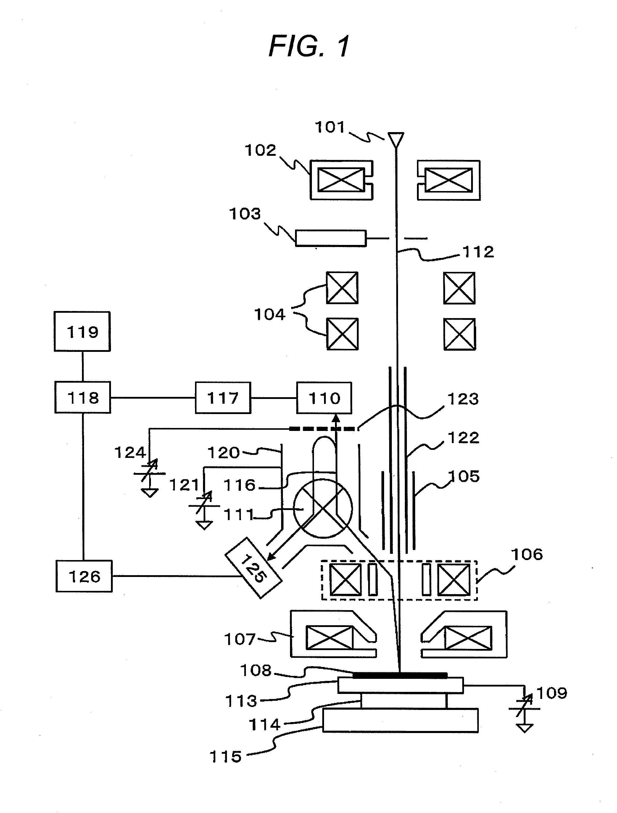
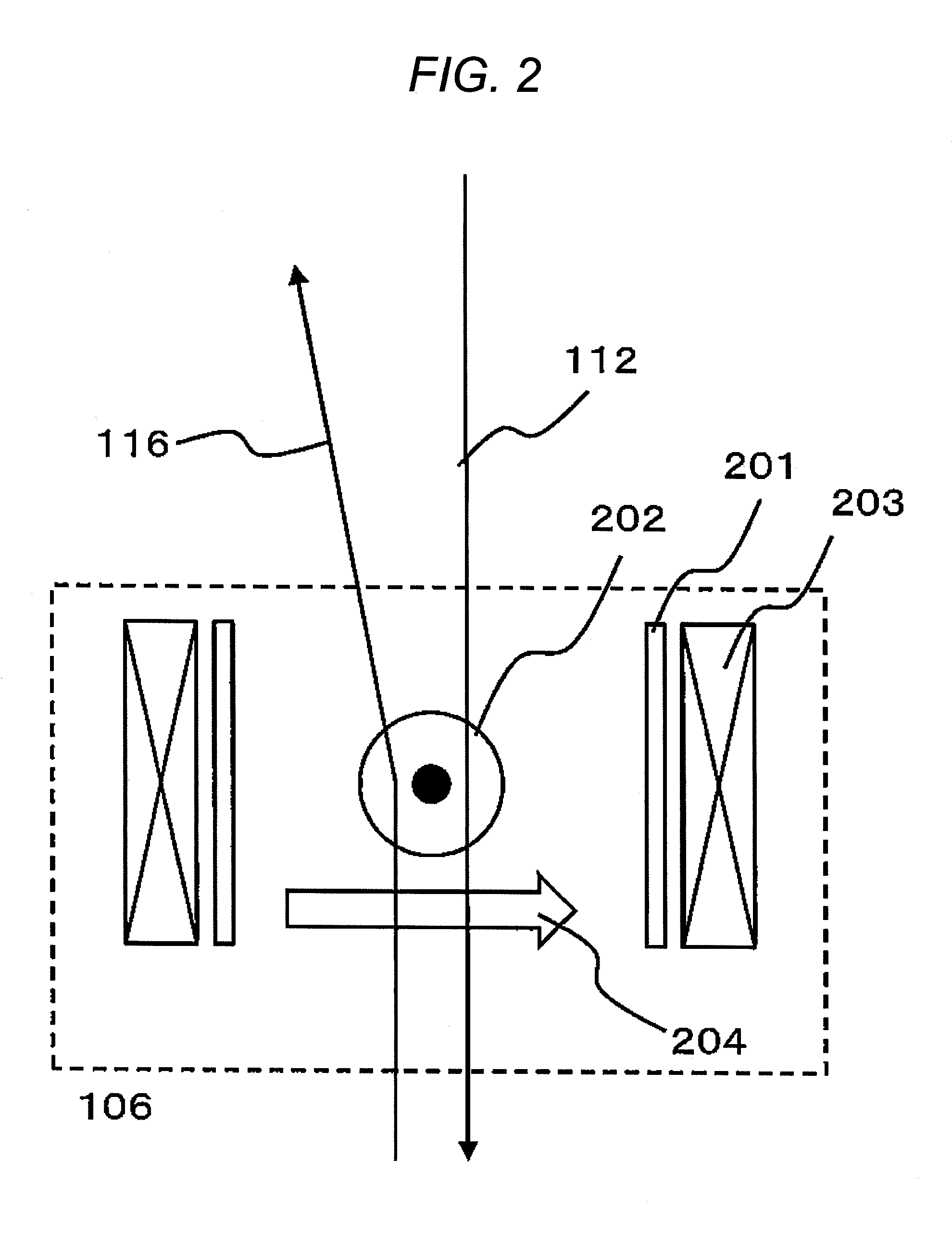
[0050]FIG. 1 is a diagram illustrating a configuration of an SEM according to the present embodiment. In the SEM of FIG. 1, primary electrons 112 generated in an electronic source 101 are condensed by a first condenser lens 102, pass through an aperture 103, are deflected in a deflector 104, pass through an electric field shield 122, pass an ExB deflector 106, are condensed narrow by an object lens 107, and are then incident on sample 108.
[0051]The sample 108 is placed on a sample holder 113, and the sample 108 and the sample holder 113 are electrically contacted. A retarding voltage (VR) can be applied to the sample holder 113 by a retarding power source 109, and the primary electrons 112 are decelerated by the retarding voltage and are incident on the sample 108. Hereinafter, the voltage applied by the retarding power source 109 is VR (<0).
[0052]A sample stage 115 can be moved in an xy plane where an optical axis of the primary electrons 112 is z axis. Further, the sample holder 1...
second embodiment
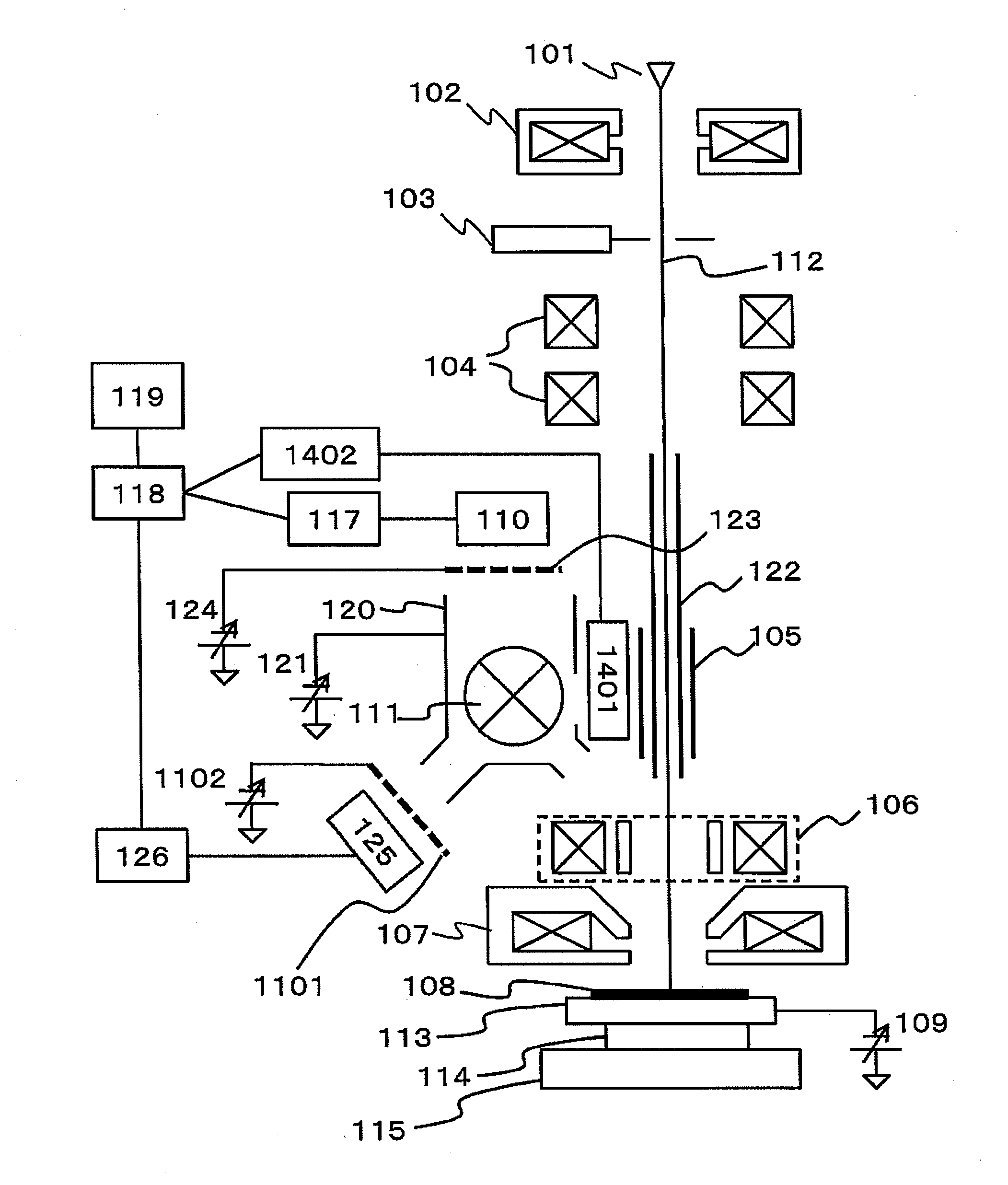
[0088]A configuration of a second embodiment will be illustrated in FIG. 11. In the present embodiment, an energy filter B1101 and a filter power source B1102 are added to the first embodiment. Here, configurations of the energy filter B1101 and the filter power source B1102 are equal to that of the energy filter A123 and the filter power source A (FIG. 6), and the energy filter B1101 is disposed at the magnetic generator 111 side of the detector B125.
[0089]The first embodiment has a configuration in which the secondary electrons passing through the energy filter A123 and the secondary electrons reflected at the energy filter A123 are respectively detected in the detector A110 and the detector B125. Meanwhile, in the present embodiment, detection of secondary electrons in an arbitrary range, in other words, bandpath detection becomes possible.
[0090]A reason why the bandpath detection becomes possible in the present embodiment will be described with reference to FIG. 12. In the prese...
third embodiment
[0097]FIG. 14 illustrates a configuration of a third embodiment. In the present embodiment, a detector C1401 and an image processor C1402 are added to the configuration of the second embodiment. Note that, in the present embodiment, a secondary electron decelerating electrode 120 has an opening in a direction of the detector C1401.
[0098]In the present embodiment, as the detector C1601, the Everhart-Thornley detector is used, similarly to the detectors A110 and B125. However, the effects of the present embodiment can be obtained even if other electron beam detectors are used for the detector C1601, such as a semiconductor detector or a micro channel plate.
[0099]The method of forming an SEM image in the detector C1601 is similar to the cases of the detectors A110 and B125. That is, the primary electron 112 is deflected by the deflector 104 so that the primary electron 112 scans the sample 108, and a signal detected in the detector C1401 is sent to the image processor C1402. In the ima...
PUM
 Abstract
Description
Claims
Application Information
 - R&D
- Intellectual Property
- Life Sciences
- Materials
- Tech Scout
- Unparalleled Data Quality
- Higher Quality Content
- 60% Fewer Hallucinations
Browse by: Latest US Patents, China's latest patents, Technical Efficacy Thesaurus, Application Domain, Technology Topic, Popular Technical Reports.
© 2025 PatSnap. All rights reserved.Legal|Privacy policy|Modern Slavery Act Transparency Statement|Sitemap|About US| Contact US: help@patsnap.com


