Apparatus and methods of energy efficient, atrial-based Bi-ventricular fusion-pacing

a bi-ventricular fusion and atrial fusion technology, applied in the field of atrial fusion pacing and apparatus, can solve the problems of not always effective delivery of crt and inability to pre-exci

Active Publication Date: 2005-09-22
MEDTRONIC INC
View PDF24 Cites 54 Cited by
  • Summary
  • Abstract
  • Description
  • Claims
  • Application Information

AI Technical Summary

Benefits of technology

[0012] A variety of locations for the atrial lead can be used successfully in practicing the methods of the present invention. For example, electrical communication (e.g., pacing and sensing an atrial chamber) with the RA can utilize an epicardial or endocardial location and any appropriate sensing vector. Similarly, the intrinsic depolarization of the ventricle can utilize any known sensing vector (e.g., tip-to-ring, coil-to-can, coil-to-coil, etc.). An endocardial location may include the common RA pacing site of the RA appendage although RA septal or other locations are acceptable. An electrode operatively coupled to the LA may also be used, including such locations as the CS and portions distal to the os of the CS, as well as the inter-atrial septal wall, among others. The locations at which the RV and LV leads couple with the myocardium can vary within each chamber, and depending on whether the patient has an RBBB or an LBBB will influence how this therapy is implemented to achieve intraventricular synchrony within the chamber where the bundle branch block occurs. In the case of LBBB, a lead operatively coupled to the RV is used to sense intrinsic depolarizations for determining the timing needed for the operative pacing interval (e.g., A-LVp interval). This lead may be used in a variety of endocardial or epicardial locations and more than one electrical lead and / or more than one pair of pace / sense electrodes may be operatively coupled to a single cardiac chamber. With respect to endocardial locations, RV apical, RV outflow tract (RVOT), RV septal, RV free wall and the like will provide benefits according to the present invention. In the case of RBBB, a lead can be operatively positioned in or near the epicardium or endocardium of the LV for sensing intrinsic depolarizations used to determine the operative pacing timing.

Problems solved by technology

However, due to a number of factors (e.g., the amount of time required for appropriate signal processing, confounding conduction delays or conduction blockage of a patient, diverse electrode placement locations, and the like) for a variety of patients the system described may not always effectively delivery CRT.
The challenge in such a system is determining the appropriate moment to delivery the single ventricular pacing stimulus, especially since such timing can be expected to vary with the timing dependent on the physiologic status of the patient (e.g., exercise, medications etc).
Heretofore, such pre-excitation was not possible because in the prior art, the fusion-pacing stimulus was triggered by a sensed event in the opposite chamber.

Method used


Image

  • Apparatus and methods of energy efficient, atrial-based Bi-ventricular fusion-pacing
  • Apparatus and methods of energy efficient, atrial-based Bi-ventricular fusion-pacing
  • Apparatus and methods of energy efficient, atrial-based Bi-ventricular fusion-pacing

Examples


Embodiment Construction

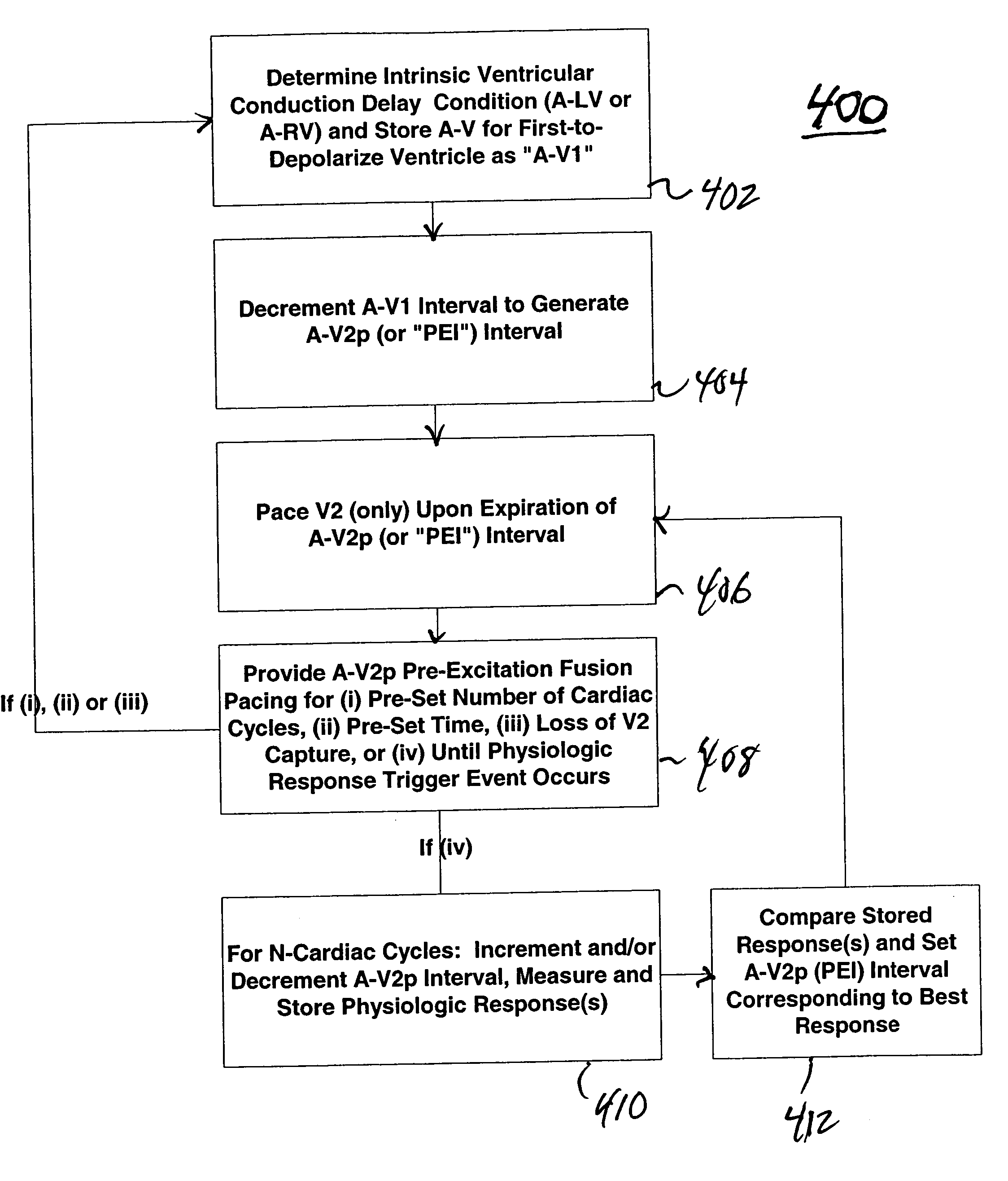
[0024] In the following detailed description, references are made to illustrative embodiments for carrying out an energy efficient, single-pacing stimulus, ventricular pre-excitation pacing mode according to the present invention. It is understood that other embodiments may be utilized without departing from the scope of the invention. For example, the invention is disclosed in detail herein in the context of an intrinsically-based or AV sequential (evoked) uni-ventricular pacing system with dual ventricular sensing that operates in an atrial tracking, demand and / or triggered pacing modes. The present invention provides an efficient pacing modality for restoring electromechanical ventricular synchrony based upon either atrial-paced or atrial-sensed events particularly for patients with some degree of either chronic, acute or paroxysmal ventricular conduction block (e.g., intraventricular, LBBB, RBBB). Cardiac pacing apparatus, according to the invention, are programmable to optional...


PUM


Abstract

The present invention enables hemodynamic efficiencies for patients suffering from intraventricular conduction delays or conduction blockage. The invention effectively overcomes such conduction delay or block (e.g., left bundle branch block, “LBBB,” or right bundle branch block, “RBBB”) by delivering a novel form of cardiac resynchronization therapy (CRT). Specifically, a single ventricular pre-excitation pacing stimulus is triggered from an atrial event (e.g., intrinsic or evoked depolarization). The triggering event may emanate from the right atrium (RA) or the left atrium (LA). A single ventricular pre-excitation pacing stimulus is delivered prior to the intrinsic depolarization of the other ventricle and thus promotes intraventricular electromechanical synchrony during CRT delivery.

Description

CROSS REFERENCE TO RELATED APPLICATIONS [0001] This patent application relates to a co-pending non-provisional U.S. patent application by Hill, namely Ser. No. 10 / 000,474 (Atty. Dkt. P-8968.00) filed 26 Oct. 2001 and entitled, “System and Method for Bi-Ventricular Fusion-pacing;” a non-provisional U.S. patent application by Pilmeyer and van Gelder; namely Ser. No. 10 / ______ (Atty. Dkt. P-11417.00) filed 17 Mar. 2004, and entitled, “APPARATUS AND METHODS FOR ‘LEPARS’ INTERVAL-BASED FUSION-PACING;” and a non-provisional U.S. patent application by B. Ferek-Petric; namely Ser. No. 10 / ______ (Atty. Dkt. P-9468.00) filed 17 Mar. 2004, and entitled, “MECHANICAL SENSING SYSTEM FOR CARDIAC PACING AND / OR FOR CARDIAC RESYNCHRONIZATION THERAPY,” the entire contents of each is hereby incorporated by reference herein.FIELD OF THE INVENTION [0002] The invention pertains to cardiac resynchronization pacing systems. In particular, the invention relates to apparatus and methods for automatically adju...

Claims


Application Information

Patent Timeline
Patent Type & Authority Applications(United States)
IPC IPC(8): A61N1/362A61N1/365A61N1/368
CPCA61N1/3682A61N1/3627A61N1/3684A61N1/36843
Inventor BURNES, JOHN E.MULLEN, THOMAS J.
Owner MEDTRONIC INC
Why Eureka
Try Eureka