Automatic hydraulic load leveling system for a work vehicle

a technology of automatic hydraulic load leveling and work vehicle, which is applied in the field of hydraulic systems, can solve the problems of inexperienced operators, difficult coordination of maneuvers, and simultaneous operation

Inactive Publication Date: 2005-09-29
HUSCO INT INC
View PDF21 Cites 35 Cited by
  • Summary
  • Abstract
  • Description
  • Claims
  • Application Information

AI Technical Summary

Benefits of technology

[0012] A method is provided for controlling movement of a load carrier to prevent a load from falling off as the boom moves up and down. The load carrier is pivotally attached to the boom which in turn is pivotally mounted on a machine chassis,...

Problems solved by technology

Such simultaneous, coordinated maneuvers can be dif...

Method used


Image

  • Automatic hydraulic load leveling system for a work vehicle
  • Automatic hydraulic load leveling system for a work vehicle
  • Automatic hydraulic load leveling system for a work vehicle

Examples


Embodiment Construction

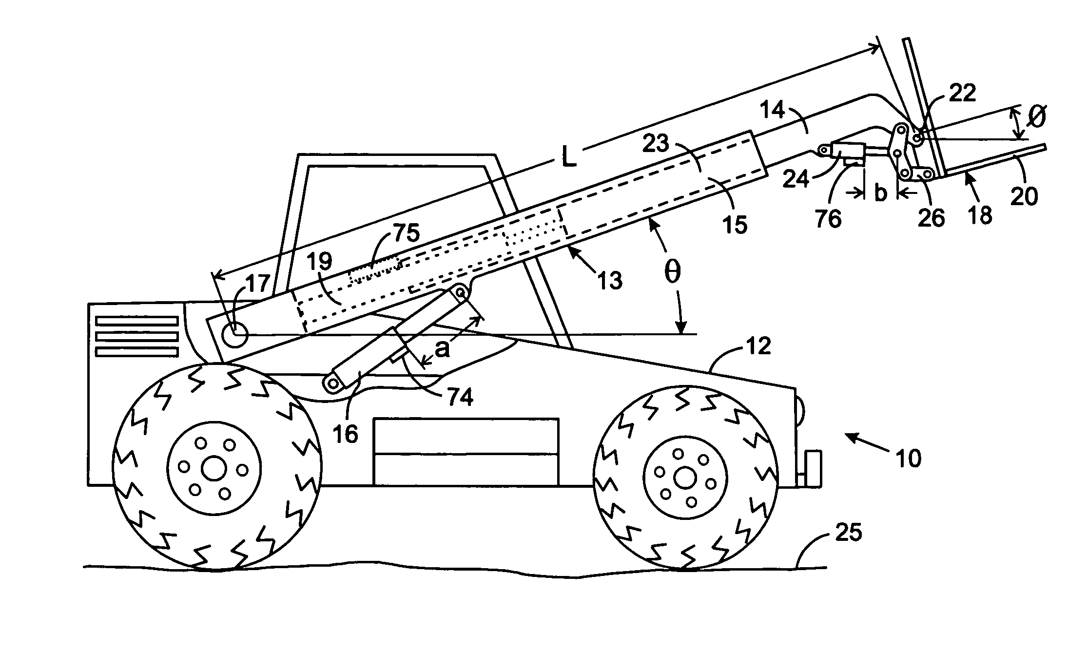
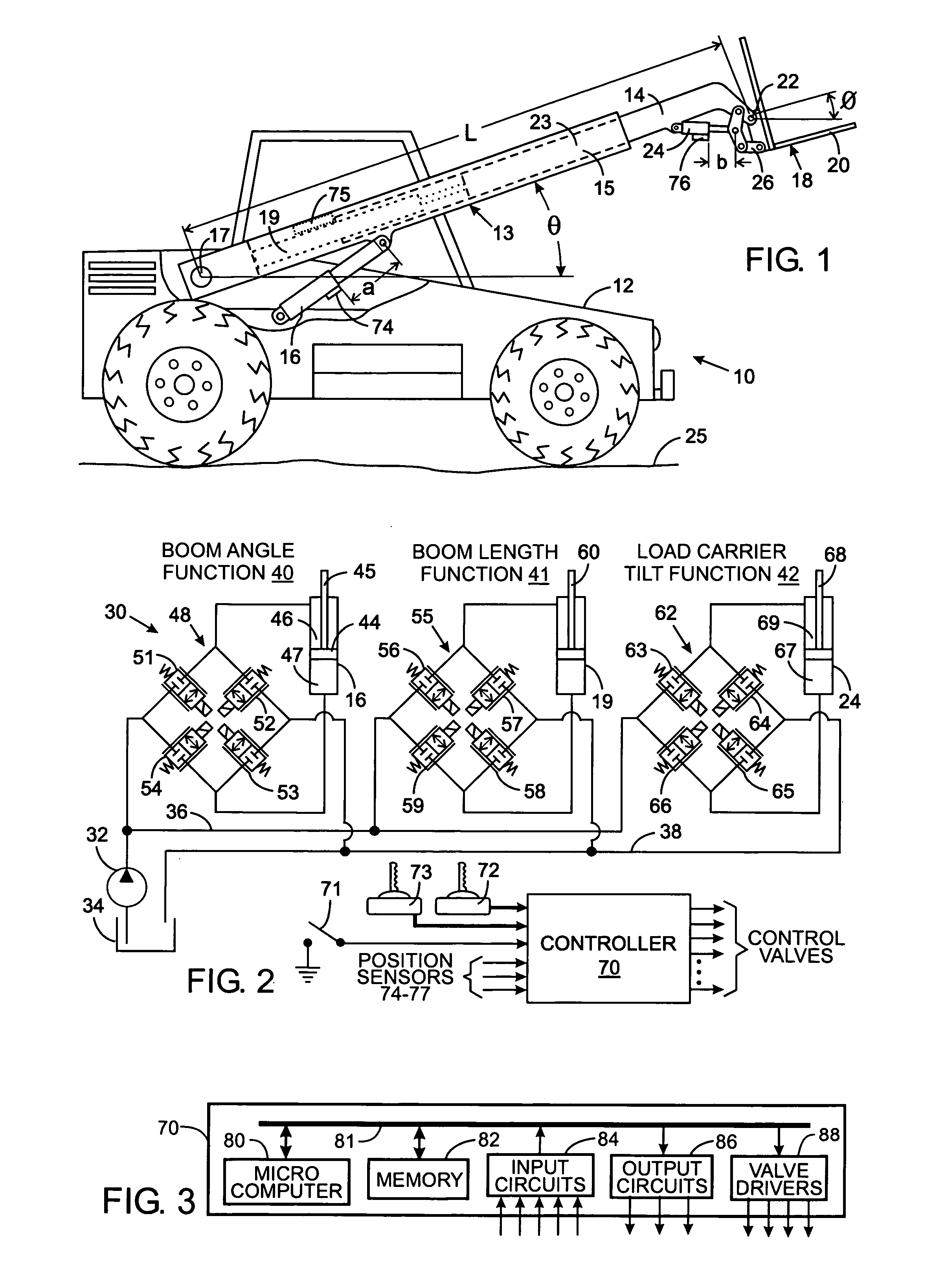
[0023] With initial reference to FIG. 1, the automatic load leveling system according to the present invention is incorporated on a telehandler 10 that comprises a chassis 12 of a vehicle on which a boom 13 is pivotally mounted. A first linear hydraulic actuator, such as a lift cylinder 16, raises and lowers the boom 13 in an arc about a pivot shaft 17, thereby varying the lift angle θ of the boom with respect to the chassis 12. The boom 13 comprises first and second sections 14 and 15 that can be extended and retracted telescopically in response to operation of a second linear hydraulic actuator, such as a length cylinder 19 within the boom. The length cylinder 19 can be directly connected to the first and second boom sections 14 and 15, as illustrated, or alternatively connected to the first section by a mechanism, such as a block and tackle, that provides a mechanical advantage.

[0024] A load carrier 18, such a pair of pallet forks 20 or a platform for lifting items or a person, ...


PUM


Abstract

A machine has a boom, that is pivotally raised and lowered by a first cylinder, and has a load carrier that is pivoted at the end of the boom by a second cylinder. As a machine operator commands movement of the boom, the position of the load carrier is automatically altered by a controller to prevent a load from falling off the load carrier. The load carrier position with respect to the boom is altered in response to the amount of boom motion to maintain a constant position relationship between the load carrier and a chassis of the machine. Although the boom and load carrier move through different angular positions, the machine control is expressed in terms of the linear motion of the first and second cylinders.

Description

CROSS-REFERENCE TO RELATED APPLICATIONS [0001] Not Applicable STATEMENT REGARDING FEDERALLY SPONSORED RESEARCH OR DEVELOPMENT [0002] Not Applicable BACKGROUND OF THE INVENTION [0003] 1. Field of the Invention [0004] The present invention relates to hydraulic systems, and in particular to such systems that control hydraulic actuators on a work vehicle to maintain a predefined angular position of a load carrier as the load is raised and lowered. [0005] 2. Description of the Related Art [0006] Construction and agricultural machines employ hydraulic systems to operate different mechanical elements. For example, a telehandler is a common material handling machine that has a pair of forks or a platform attached to the end of a telescopic boom pivotally attached to a tractor. Separate hydraulic actuators are employed to change the pivot angle, i.e. raise and lower the boom, and change the length of the boom, with each of those operations being referred to as a “function” of the machine. An...

Claims


Application Information

Patent Timeline
IPC IPC(8): B66F9/00B66F9/065B66F9/22E02F1/00E02F3/43E02F9/22
CPCB25J9/1628B66F9/0655B66F9/22G05B2219/45049G05B2219/39217G05B2219/41273G05B2219/45017E02F3/432
Inventor MENNEN, KENNETH C.PFAFF, JOSEPH L.
Owner HUSCO INT INC
Why Eureka
Try Eureka