Solenoid plunger cushioning system for a washing machine balancing fluid valve

a technology of balancing fluid valve and plunger, which is applied in the field of valves, can solve the problems of repeated operation of this type of solenoid and is extremely hard on the internal components of the solenoid, and achieve the effects of reducing the effect, reducing the voltage, and ensuring the effect of fluid dispensed

Inactive Publication Date: 2005-09-29
MAYTAG
View PDF19 Cites 13 Cited by
  • Summary
  • Abstract
  • Description
  • Claims
  • Application Information

AI Technical Summary

Benefits of technology

[0013] Certainly, injecting balancing fluid from stationary injectors into receptacles arranged about a spinning inner tub requires precise timing. Accordingly, in order to meet these stringent timing requirements, the injector valve must be operated rapidly, and repeatedly in order to achieve proper correction of the out-of-balance condition. Repeated operation of this type is extremely hard on internal components of the solenoid. Therefore, in accordance with one aspect of the invention, a cushion is mounted to an end portion of the solenoid plunger. In a more preferred form, a groove or annular ring is formed in the end of the plunger and sized to receive a resilient, elastomeric annular ring. Once in place, the annular ring reduces the effects of the repeated impacts between the plunger and a pole piece or end portion of the coil body.
[0014] In accordance with another aspect of the invention, the pole piece undergoes a texturing process to roughen the impact surface. Examples of acceptable texturing include cross-hatching, knurling, rough sanding and the placement of grooves in the surface. With this arrangement, a leakage pa...

Problems solved by technology

Repeated operation of this type is extrem...

Method used


Image

  • Solenoid plunger cushioning system for a washing machine balancing fluid valve
  • Solenoid plunger cushioning system for a washing machine balancing fluid valve
  • Solenoid plunger cushioning system for a washing machine balancing fluid valve

Examples


Embodiment Construction

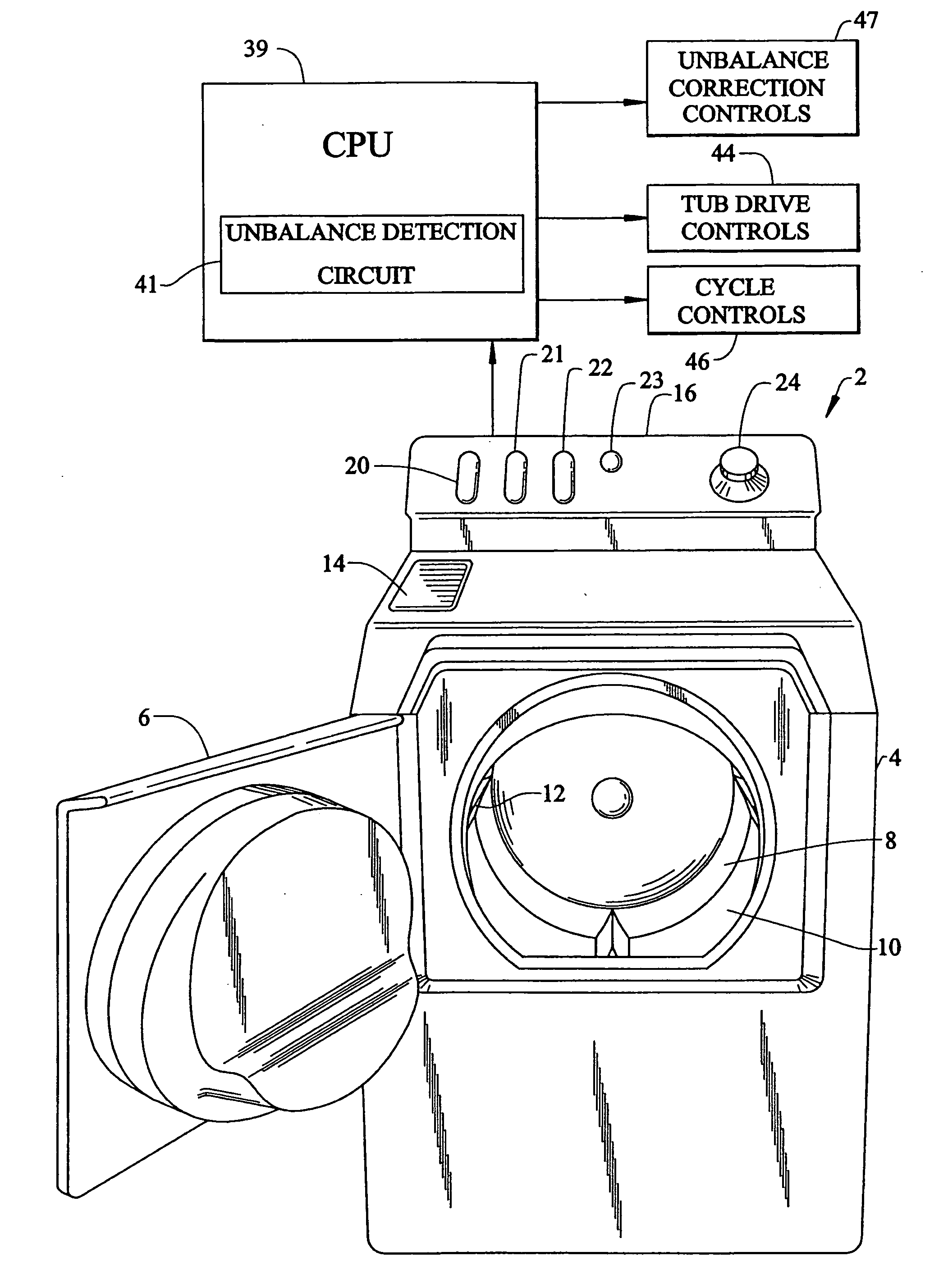
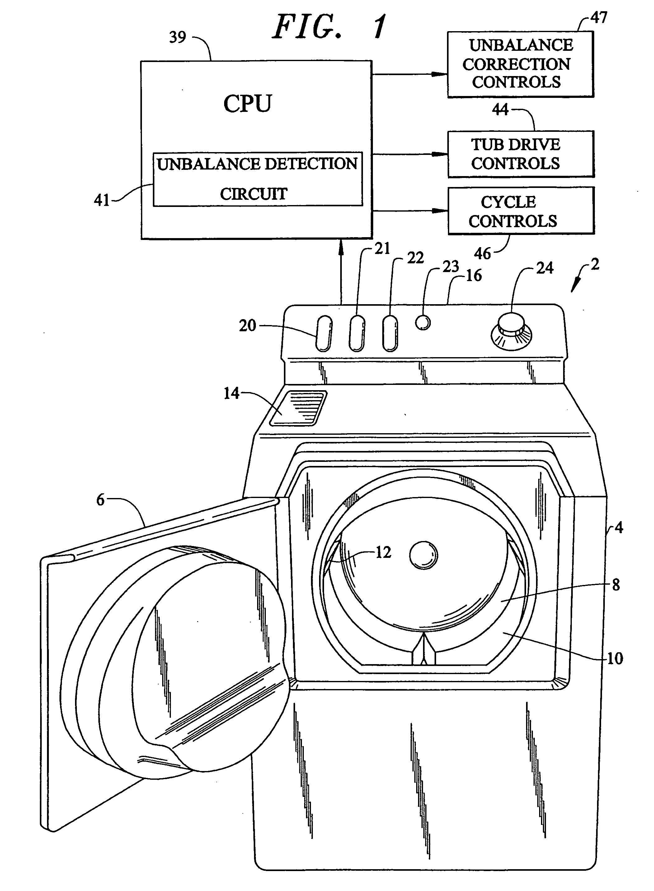
[0029] With initial reference to FIG. 1, a laundry appliance constructed in accordance with the present invention is generally indicated at 2. As shown, laundry appliance 2 constitutes a horizontal axis machine including an outer cabinet shell 4 having an associated door 6 which can be selectively opened to expose a washing basket 8. In the embodiment shown, washing basket 8, also referred to as an inner tub or spinner, is mounted within an outer tub 9 (FIG. 2) in cabinet shell 4 for rotation about an axis which is angled slightly downward toward a rear portion of cabinet shell 4. For the sake of completeness, inner tub 8 is shown to include a plurality of holes 10, as well as various generally triangular shaped and radially inwardly projecting fins or blades 12 which are fixedly secured to an internal peripheral portion of inner tub 8. In a manner known in the art, inner tub 8 is adapted to rotate during both wash and rinse cycles, such that articles of clothing placed therein actu...


PUM


Abstract

A washing machine includes an out-of-balance correction system having a plurality of injector valves each having an associated solenoid element. Each of the injector valves is adapted to selectively inject a balancing fluid into a pocket carried by an inner tub to offset the out-of-balance condition. The valves are rapidly and repeatedly cycled to achieve a timed dispensing of the balancing fluid. To reduce the effects of the repeated cycling on the solenoid, a cushion element is mounted to a rear portion of a plunger carried within a solenoid coil. Additionally, a texturing process is applied to a pole piece arranged within the solenoid coil to establish a controlled leakage of air from a central portion of the cushion element once the plunger contacts the pole piece. With this arrangement, the service life of the injector valve is increased and proper control and timing of the injector valve is assured.

Description

BACKGROUND OF THE INVENTION [0001] 1. Field of the Invention [0002] The present invention pertains to the art of valves and, more particularly, to a solenoid plunger cushioning system for use in a balancing fluid injection valve for selectively dispensing a balancing fluid into a rotating inner tub of a washing machine. [0003] 2. Discussion of the Prior Art [0004] During operation of a washing machine, it is not uncommon for an inner tub or spinner, which is rotatably mounted within the washing machine, to become unbalanced due to a particular distribution of a load of laundry. During the course of a typical wash cycle, the inner tub is rotated at a relatively high or extraction speed to extract water absorbed by the laundry. If the laundry is unevenly distributed within the inner tub during the extraction phase, an out-of-balance condition will develop. This out-of-balance condition, when rotated at the extraction speed, can cause excessive vibration. [0005] Certainly, excessive vi...

Claims


Application Information

Patent Timeline
IPC IPC(8): D06F33/48D06F34/08D06F35/00D06F37/20D06F37/22D06F37/24
CPCD06F35/007D06F37/245D06F37/225D06F33/48D06F34/08
Inventor CONTINI, VINCENT J.GEORGE, PAUL E. IIGLENN, BRADLEY CHARLES
Owner MAYTAG
Why Eureka
Try Eureka