Apparatus and method for thermally developing flexographic printing elements

a technology of flexographic printing and apparatus, which is applied in the field of method and apparatus for thermally developing flexographic printing elements, can solve the problems of loss of accuracy, method can be used, and additional machine and more tim

Active Publication Date: 2005-09-29
MACDERMID PRINTING SOLUTIONS
View PDF22 Cites 39 Cited by
  • Summary
  • Abstract
  • Description
  • Claims
  • Application Information

AI Technical Summary

Benefits of technology

[0024] The present invention comprises an improved thermal development apparatus and a method of using the improved thermal development apparatus to remove uncured photopolymer from the imaged surface of a flexographic printing element. In another embodiment, the present invention comprises an improved ap

Problems solved by technology

The drawback to many of the current methods of thermal development is that these methods can be used only on flat plates, which must then be mounted after development.
This operation requires an additional machine and more time and can also result in a loss in accuracy when registration between multiple plates and colors is required.
This increases the difficulty in making printing elements of different sizes.
In addition, additional problems may arise when attempting to make the blotting machine larger to accommodate larger printing elements.
Another problem with the current blotting methods i

Method used


Image

  • Apparatus and method for thermally developing flexographic printing elements
  • Apparatus and method for thermally developing flexographic printing elements
  • Apparatus and method for thermally developing flexographic printing elements

Examples


Embodiment Construction

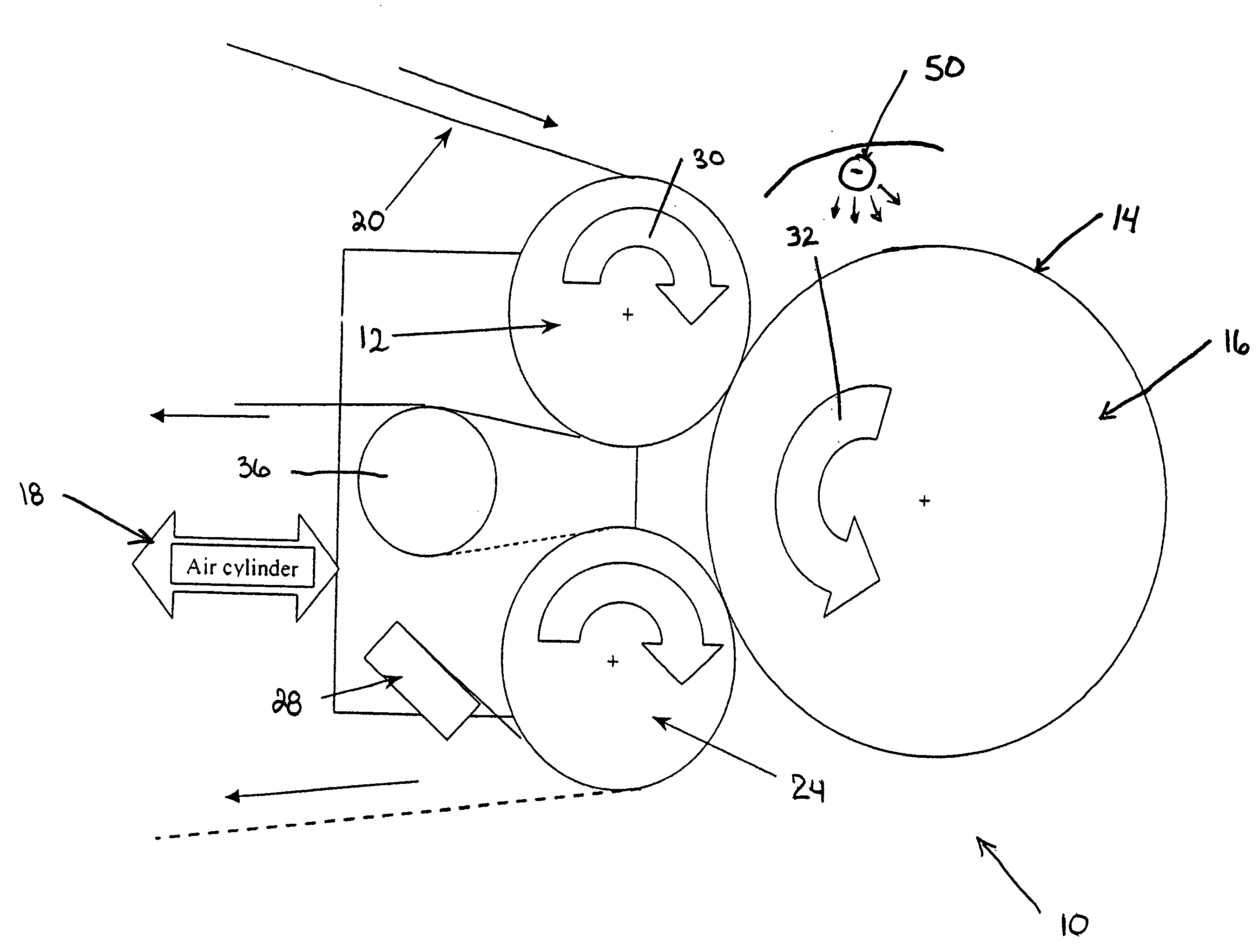
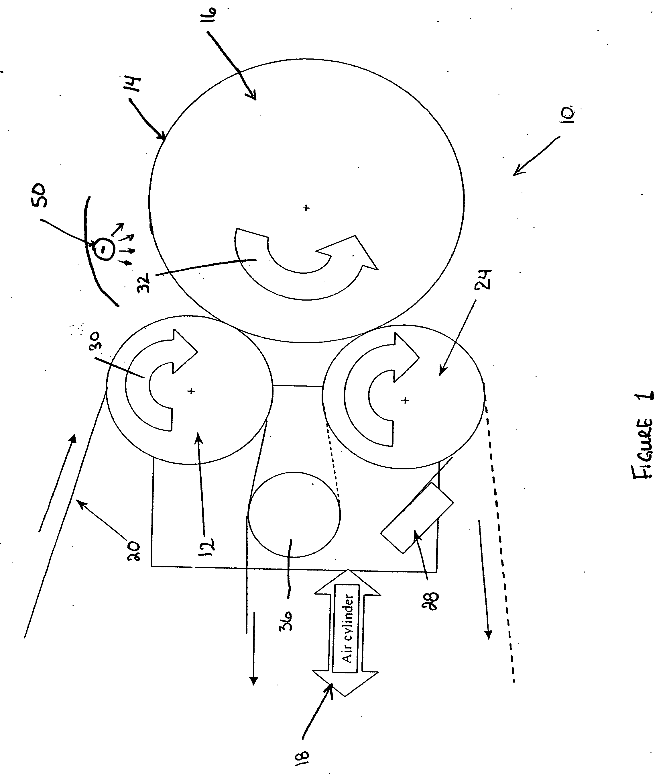
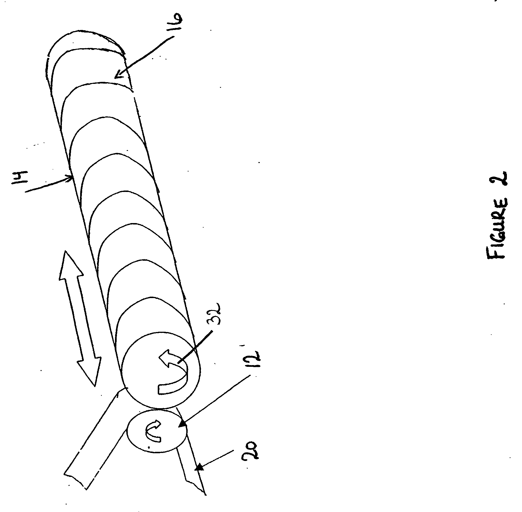
[0047] The present invention relates to an improved thermal development apparatus and a method of using the apparatus to remove non-crosslinked polymer from an imaged surface of a relief image printing element during a process for manufacturing the relief image printing element.

[0048] In another embodiment, the present invention relates to an improved combined exposing and developing apparatus and a method of using the apparatus to expose the relief image printing plate to actinic radiation to selectively cure, i.e. crosslink, portions of the photopolymer layer revealed during the imaging step, and thermally developing the relief image printing plate to remove non-crosslinked polymer from the imaged and exposed surface of the relief printing element during a process for manufacturing the relief image printing element.

[0049] The present invention also relates to an improved combined exposing, developing, and post exposure / detack apparatus and a method of using the combined apparatu...


PUM

PropertyMeasurementUnit
Temperatureaaaaaaaaaa
Lengthaaaaaaaaaa

Abstract

An improved apparatus for thermally developing a flexographic printing element to reveal a relief image on the surface and a method of using the apparatus to expose and develop a flexographic printing element. The apparatus typically comprises means for softening or melting non-crosslinked photopolymer on the imaged and exposed surface of the flexographic printing element; at least one roll that is contactable with the imaged surface of the flexographic printing element and capable of moving over at least a portion of the imaged surface of the flexographic printing element to remove the softened or melted non-crosslinked photopolymer on the imaged and exposed surface of the flexographic printing element; and means for maintaining contact between the at least one roll and the imaged and exposed surface of the flexographic printing element. The means for softening or melting non-crosslinked photopolymer on the imaged and exposed surface of the flexographic printing element comprise a heater positioned adjacent to the imaged surface of the flexographic printing element and/or heating the at least one roll that contactable with the imaged surface of the flexographic printing element. The apparatus may also contain an exposure device to crosslink and cure the imaged surface of the flexographic printing element prior to thermal development.

Description

CROSS REFERENCE TO RELATED APPLICATIONS [0001] This application is a continuation-in-part of co-pending patent application Ser. No. 10 / 811,763, filed Mar. 29, 2004, the subject matter of which is herein incorporated by reference in its entirety.FIELD OF THE INVENTION [0002] The present invention is directed to a method and an apparatus for thermally developing flexographic printing elements, including printing plates and printing sleeves. BACKGROUND OF THE INVENTION [0003] Flexography is a method of printing that is commonly used for high-volume runs. Flexography is employed for printing on a variety of substrates such as paper, paperboard stock, corrugated board, films, foils and laminates. Newspapers and grocery bags are prominent examples. Coarse surfaces and stretch films can be economically printed only by means of flexography. Flexographic printing plates are relief plates with image elements raised above open areas. Such plates offer a number of advantages to the printer, bas...

Claims


Application Information

Patent Timeline
IPC IPC(8): B41C1/00G03C7/36G03F7/26G03F7/34G03F7/36
CPCB41C1/05G03F7/36G03F7/34
Inventor MARKHART, GARY T.
Owner MACDERMID PRINTING SOLUTIONS
Why Eureka
Try Eureka