Composite hose with a corrugated metal tube

a technology of corrugated metal and composite hoses, which is applied in the direction of flexible pipes, mechanical devices, layered products, etc., can solve the problems of fatigue cracking of corrugated metal tubes, large stress on corrugated metal tubes, and difficult to meet the required resistance of organic materials only such as rubber or resin

Inactive Publication Date: 2005-09-29
SUMITOMO RIKO CO LTD
View PDF35 Cites 23 Cited by
  • Summary
  • Abstract
  • Description
  • Claims
  • Application Information

AI Technical Summary

Benefits of technology

[0035] In this construction, in addition to a reinforcing effect given by the second reinforcing layer, a further reinforcing effect is given by the first reinforcing layer. So, the first reinforcing layer restrains the hose, specifically the corrugated metal tube from dimensional change in a radial direction, namely deformation in the radial direction. Therefore, obtained is an effect that the corrugated metal tube is entirely restrained from deformation both in a longitudinal direction and in a radial direction.

Problems solved by technology

However, with regard to this requirement hoses configured by organic materials only such as rubber or resin are difficult to satisfy such required resistance.
Meanwhile, when an internal pressure is exerted to such composite hose with a corrugated metal tube repeatedly, the corrugated metal tube suffers a large stress, and there is a fear that thereby the corrugated metal tube is fatigue-cracked at an early stage.
And, it was found that the hose 200 does not necessarily have sufficient durability.

Method used


Image

  • Composite hose with a corrugated metal tube
  • Composite hose with a corrugated metal tube
  • Composite hose with a corrugated metal tube

Examples


example

[0089] Samples of a composite hose with a corrugated metal tube as shown in Table 1 are produced. The second reinforcing layers are constructed specifically as shown in Table 2. Then an impulse test was conducted as a durability test on the samples which were bent in U-shape in a manner shown in FIG. 5 by exerting an internal pressure thereto repeatedly under the following conditions.

Bend R (radius):70 mmTemperature:130° C.Pressure:0 22.5 MpaFrequency (pressure cycle30 cpmrepetitions / minute):Durability:Number of cycle repetitions up tobreakage of a hose

[0090]

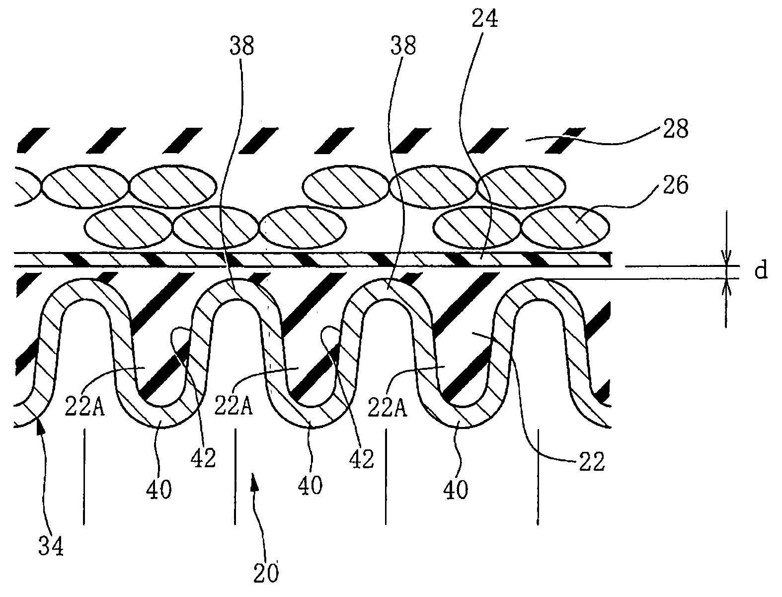
TABLE 1Construction of the sample hosesMaterialWall thickness, etc.Corrugated metal tubeSUS304t = 0.23 mmRubber filler layerEPDMt = 0.3 mm(on condition that therubber filler layer isfilled sufficiently invalley gaps)Resin layerST811(alloy oft = 0.2 mmPA6 / EPDM)First reinforcing layerAramidBraid angle 64°Middle rubber layerEPDMt = 0.5 mmSecond reinforcing layerDiameter 0.2 wireBraid angle 32°Outer surface rubber layerEPDMt = 1....


PUM

PropertyMeasurementUnit
neutral angleaaaaaaaaaa
winding angle θ1aaaaaaaaaa
winding angleaaaaaaaaaa

Abstract

A composite hose comprises a corrugated metal tube as barrier layer against permeation of conveyed fluid and a reinforcing layer which is formed by braiding a reinforcing wire member made of a metal wire. A braid density of the reinforcing layer is 55% or less.

Description

TECHNICAL FIELD [0001] The present invention relates to a composite hose with a corrugated metal tube as a barrier layer against permeation of conveyed fluid, which is preferably usable for conveying fuel in automobiles, conveying refrigerant, conveying fuel of cell such as hydrogen gas used in fuel cell or any other applications. BACKGROUND OF THE INVENTION [0002] Typical rubber hoses, for example, made of a blend of acrylonitrile-butadiene rubber and polyvinyl chloride (NBR / PVC blend) which is excellent in resistance to gasoline permeability, have been used for conveying fuel (fuel such as gasoline for engine) for automobiles or the like in view of their high vibration-absorbability, easy assembling or the like. However, for the purpose of global environment protection, the regulations have been recently tighten against permeation of fuel for automobiles or the like, and are anticipated to be further tighten in the future. Therefore, such hoses for conveying fuel are required furt...

Claims


Application Information

Patent Timeline
Patent Type & Authority Applications(United States)
IPC IPC(8): F16L11/11B32B1/08F16L9/00F16L9/14F16L11/00F16L11/08F16L11/10F16L11/14F16L11/15F16L11/20
CPCF16L11/085F16L11/15F16L11/086
Inventor TAKAGI, YUJIHIRAMATSU, MINORU
Owner SUMITOMO RIKO CO LTD
Why Eureka
Try Eureka