Method and apparatus and program storage device adapted for automatic drill string design based on wellbore geometry and trajectory requirements

a program storage device and drill string technology, applied in the direction of directional drilling, survey, borehole/well accessories, etc., can solve the problems of cumbersome calculations, cumbersome design process and system, and inability to design drill strings terribly complex,

a program storage device and drill string technology, applied in the direction of directional drilling, survey, borehole/well accessories, etc., can solve the problems of cumbersome calculations, cumbersome design process and system, and inability to design drill strings terribly complex,

US20050211468A1Active Publication Date: 2005-09-29SCHLUMBERGER TECH CORP

Image

  • Method and apparatus and program storage device adapted for automatic drill string design based on wellbore geometry and trajectory requirements
  • Method and apparatus and program storage device adapted for automatic drill string design based on wellbore geometry and trajectory requirements
  • Method and apparatus and program storage device adapted for automatic drill string design based on wellbore geometry and trajectory requirements

Examples


Embodiment Construction

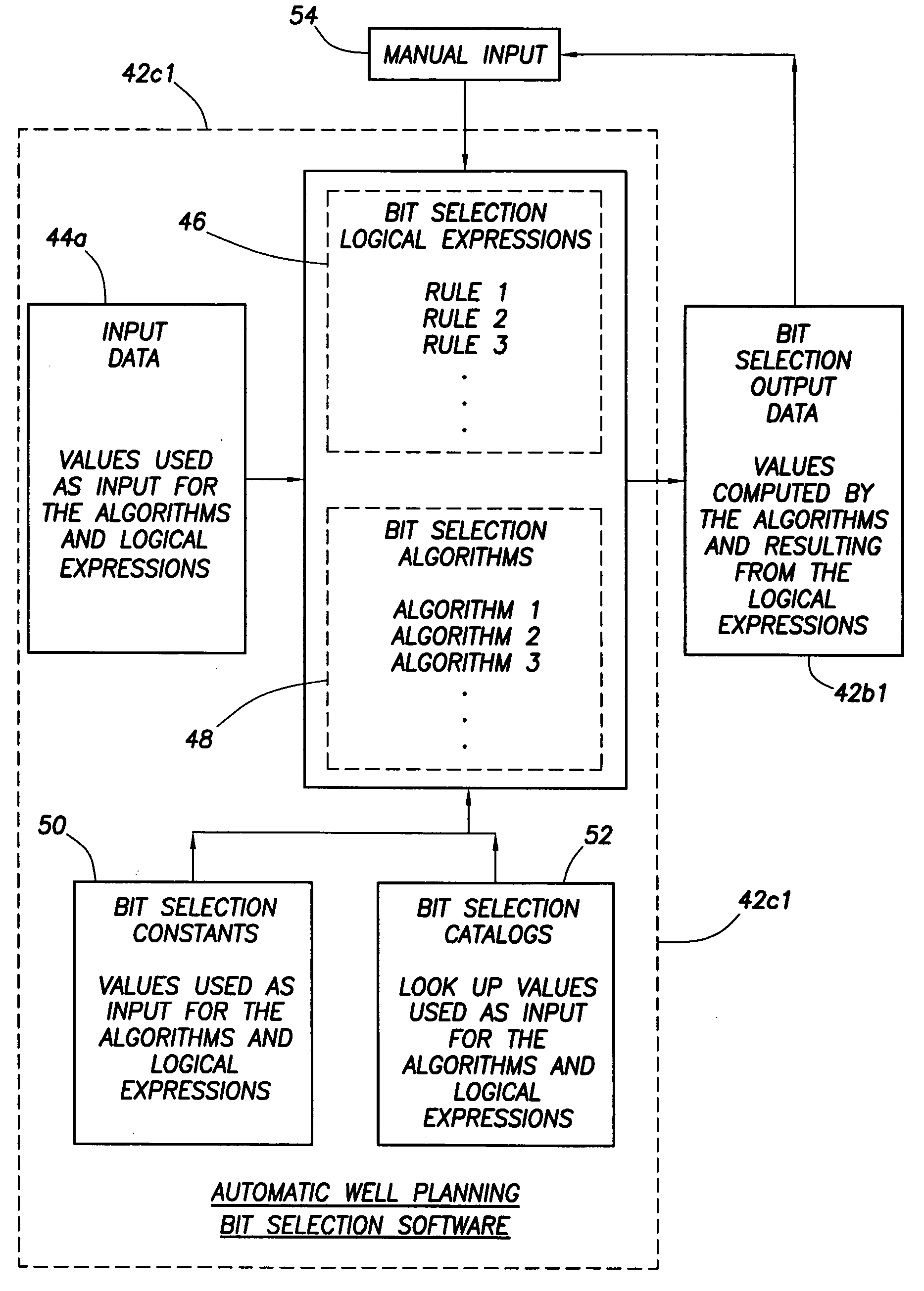
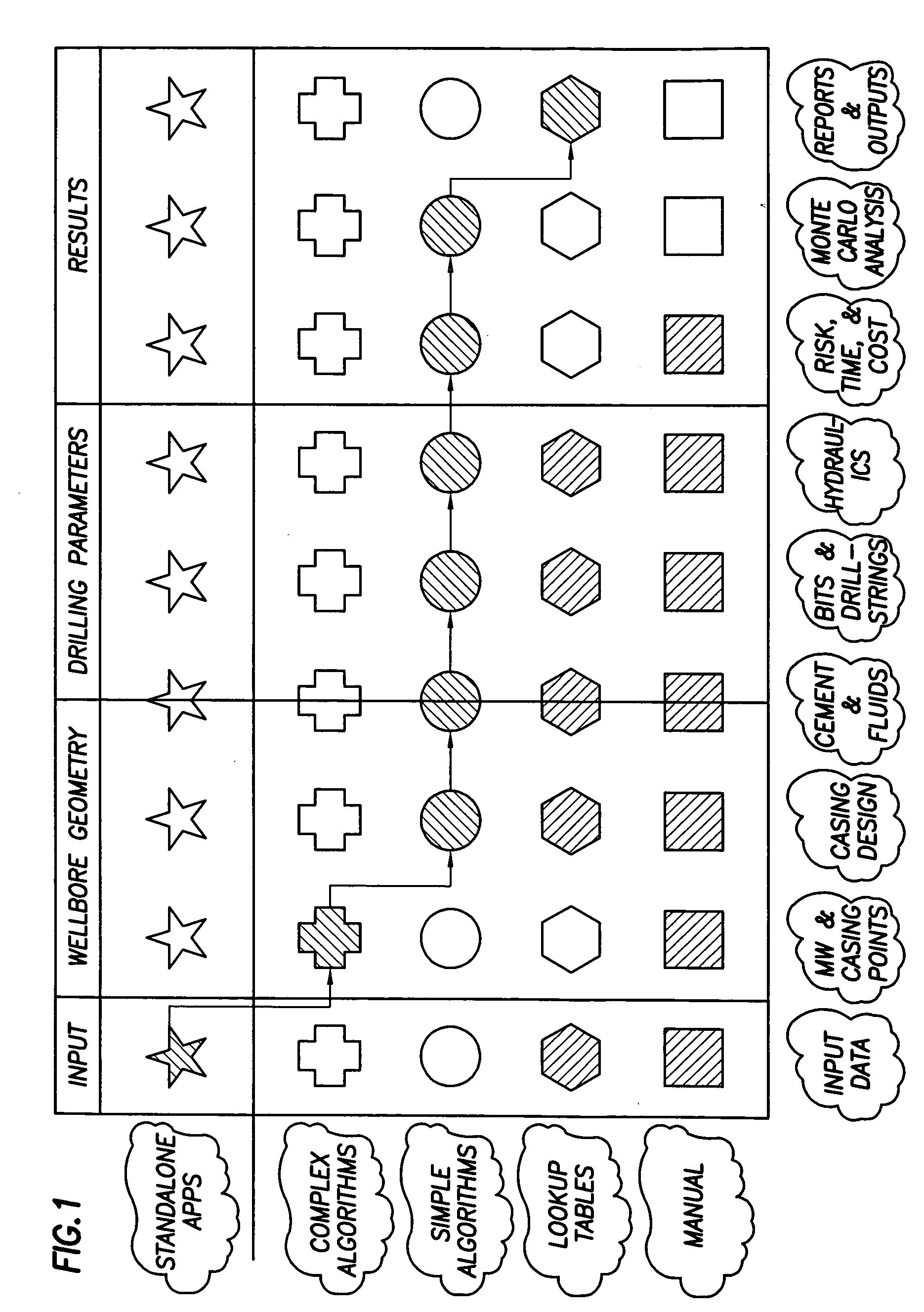
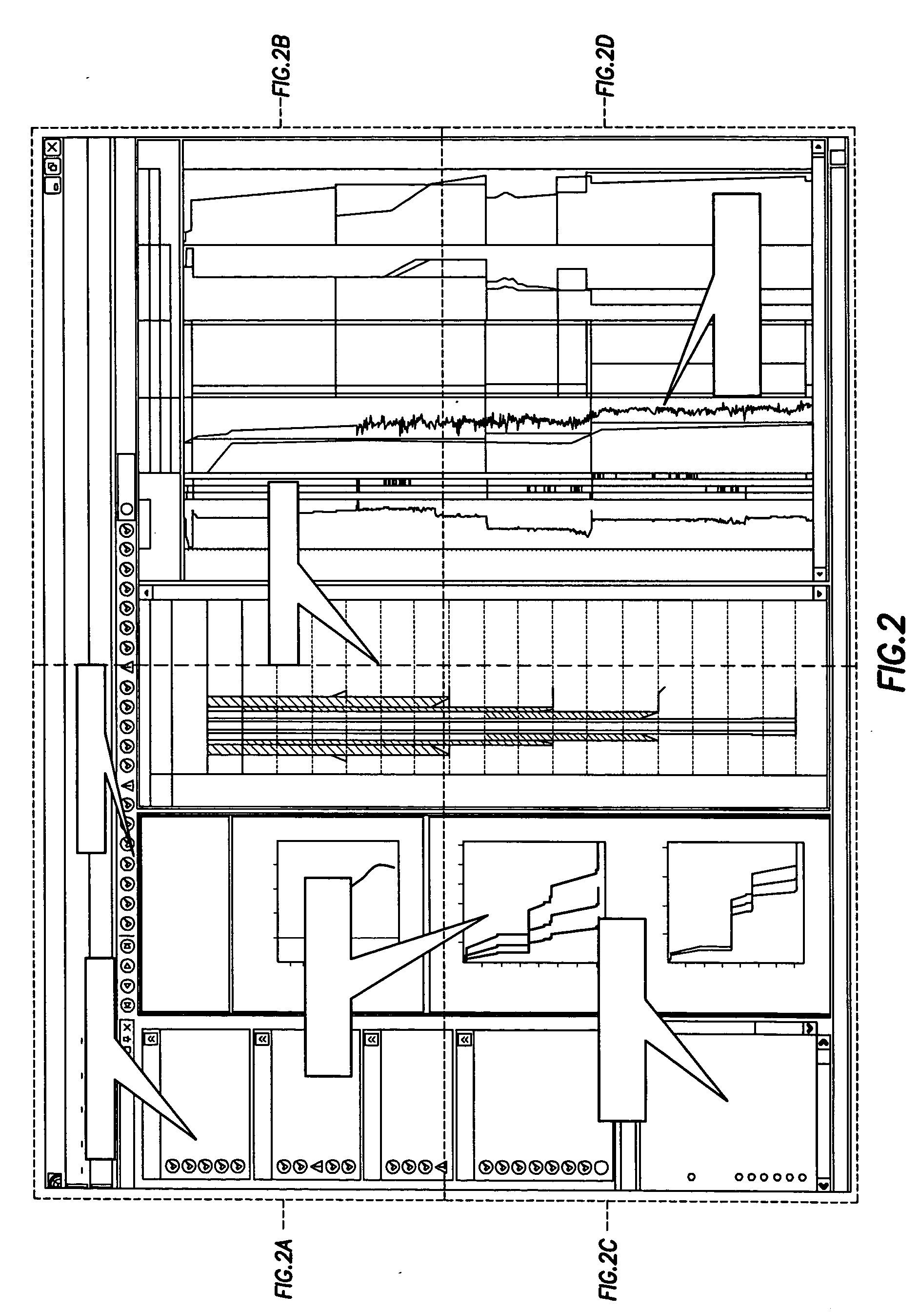
[0033] An ‘Automatic Well Planning Software System’ is disclosed in this specification. The ‘Automatic Well Planning Software System’ of the present invention is a “smart” tool for rapid creation of a detailed drilling operational plan that provides economics and risk analysis. The user inputs trajectory and earth properties parameters; the system uses this data and various catalogs to calculate and deliver an optimum well design thereby generating a plurality of outputs, such as drill string design, casing seats, mud weights, bit selection and use, hydraulics, and the other essential factors for the drilling task. System tasks are arranged in a single workflow in which the output of one task is included as input to the next. The user can modify most outputs, which permits fine-tuning of the input values for the next task. The ‘Automatic Well Planning Software System’ has two primary user groups: (1) Geoscientist: Works with trajectory and earth properties data; the ‘Automatic Well ...


PUM


Abstract

A method of generating drillstring design information in response to input data which includes wellbore geometry and wellbore trajectory requirements, comprises the step of generating a summary of a drillstring in each hole section of a wellbore in response to the input data.

Description

CROSS REFERENCE TO RELATED APPLICATIONS [0001] This application is related to pending application Ser. No. ______ filed ______, corresponding to attorney docket number 94.0075; and it is related to pending application Ser. No. ______ filed ______, corresponding to attorney docket number 94.0077; and it is related to pending application Ser. No. ______ filed ______, corresponding to attorney docket number 94.0078; and it is related to pending application Ser. No. ______ filed ______, corresponding to attorney docket number 94.0080.BACKGROUND OF THE INVENTION [0002] The subject matter of the present invention relates to a software system adapted to be stored in a computer system, such as a personal computer, for providing automatic drill string design based on wellbore geometry and trajectory requirements. [0003] Minimizing wellbore costs and associated risks requires wellbore construction planning techniques that account for the interdependencies involved in the wellbore design. The ...

Claims


Application Information

Patent Timeline
29 Sep 2005
Publication
US20050211468A1
IPC
E21B7/04; E21B41/00; E21B44/00
CPC
E21B7/04
Inventors
VEENINGEN, DAAN; GIVENS, KRIS