System and method for controlling drill motor rotational speed

a technology of rotating speed and drill shaft, which is applied in the direction of drilling rods, drilling pipes, drilling holes/well accessories, etc., can solve the problems of excessive wear of the rotor and/or other components of the drill string

Inactive Publication Date: 2005-09-29
EFFECTIVE EXPLORATION
View PDF31 Cites 50 Cited by
  • Summary
  • Abstract
  • Description
  • Claims
  • Application Information

AI Technical Summary

Benefits of technology

[0006] Technical advantages of the present invention include an improved system and method for controlling drill motor rotational speed to increase the motor's operational life. In particular, a drill motor governor is operable to directly control the flow of drilling fluid into a drill motor so as to control the rotational speed of the drill motor. The use of such a governor can prevent over-speed conditions that frequently occur when using compressible drilling fluids such as air, nitrogen, or foam. Such over-speed conditions can cause excessive wear of the rotor and / or other components of a drill string. Another technical advantage of the present invention includes the ability to allow excess drilling fluid to enter the well bore to clean the well bore without that drilling fluid passing through the drill motor. Other technical advantages of the present invention will be readily apparent to one skilled in the art from the following figures, description, and claims. Moreover, while specific advantages have been enumerated above, various embodiments may include all, some, or none of the enumerated advantages.
includes the ability to allow excess drilling fluid to enter the well bore to clean the well bore without that drilling fluid passing through the drill motor. Other technical advantages of the present invention will be readily apparent to one skilled in the art from the following figures, description, and claims. Moreover, while specific advantages have been enumerated above, various embodiments may include all, some, or none of the enumerated advantages.

Problems solved by technology

Such over-speed conditions can cause excessive wear of the rotor and / or other components of a drill string.

Method used


Image

  • System and method for controlling drill motor rotational speed
  • System and method for controlling drill motor rotational speed
  • System and method for controlling drill motor rotational speed

Examples


Embodiment Construction

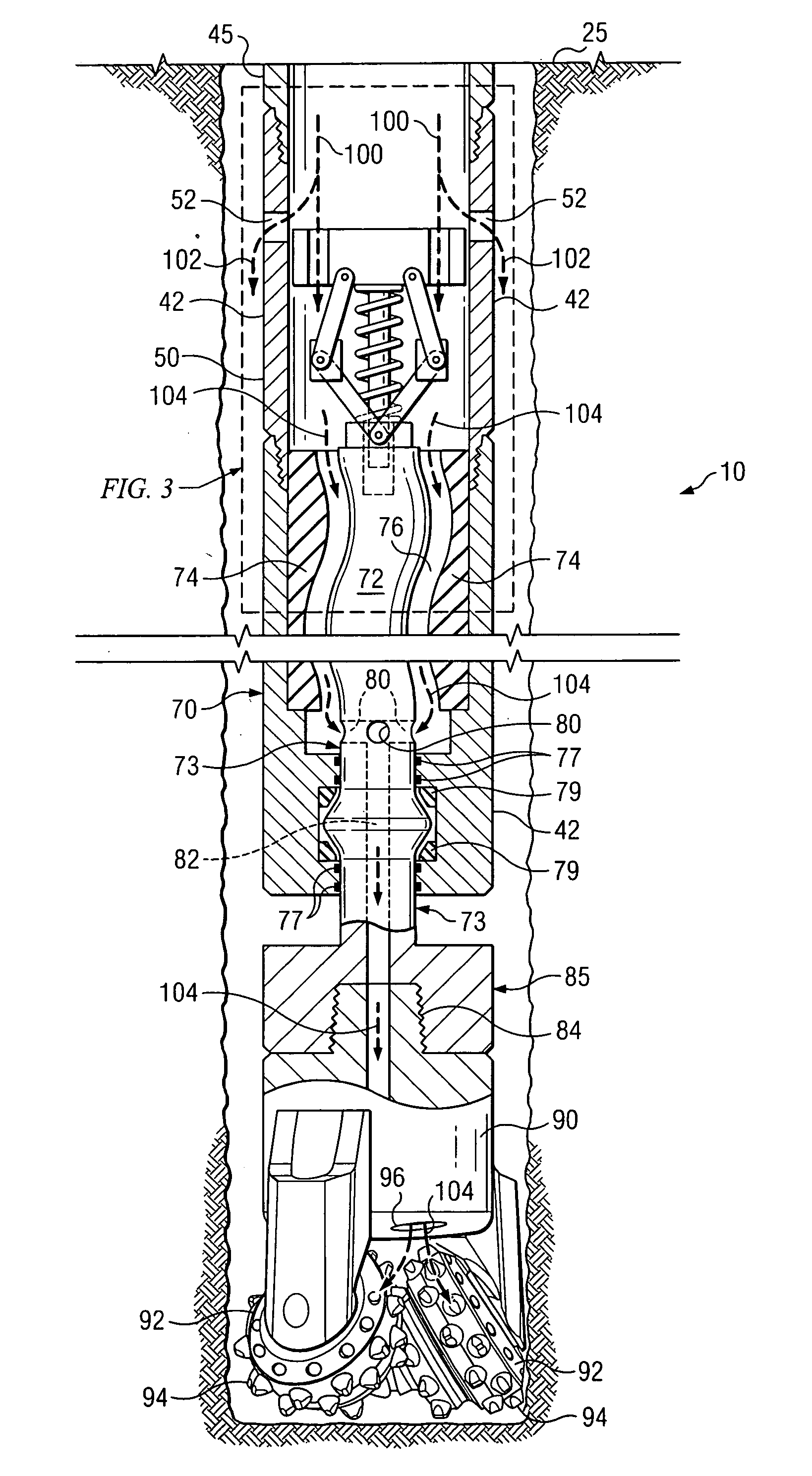
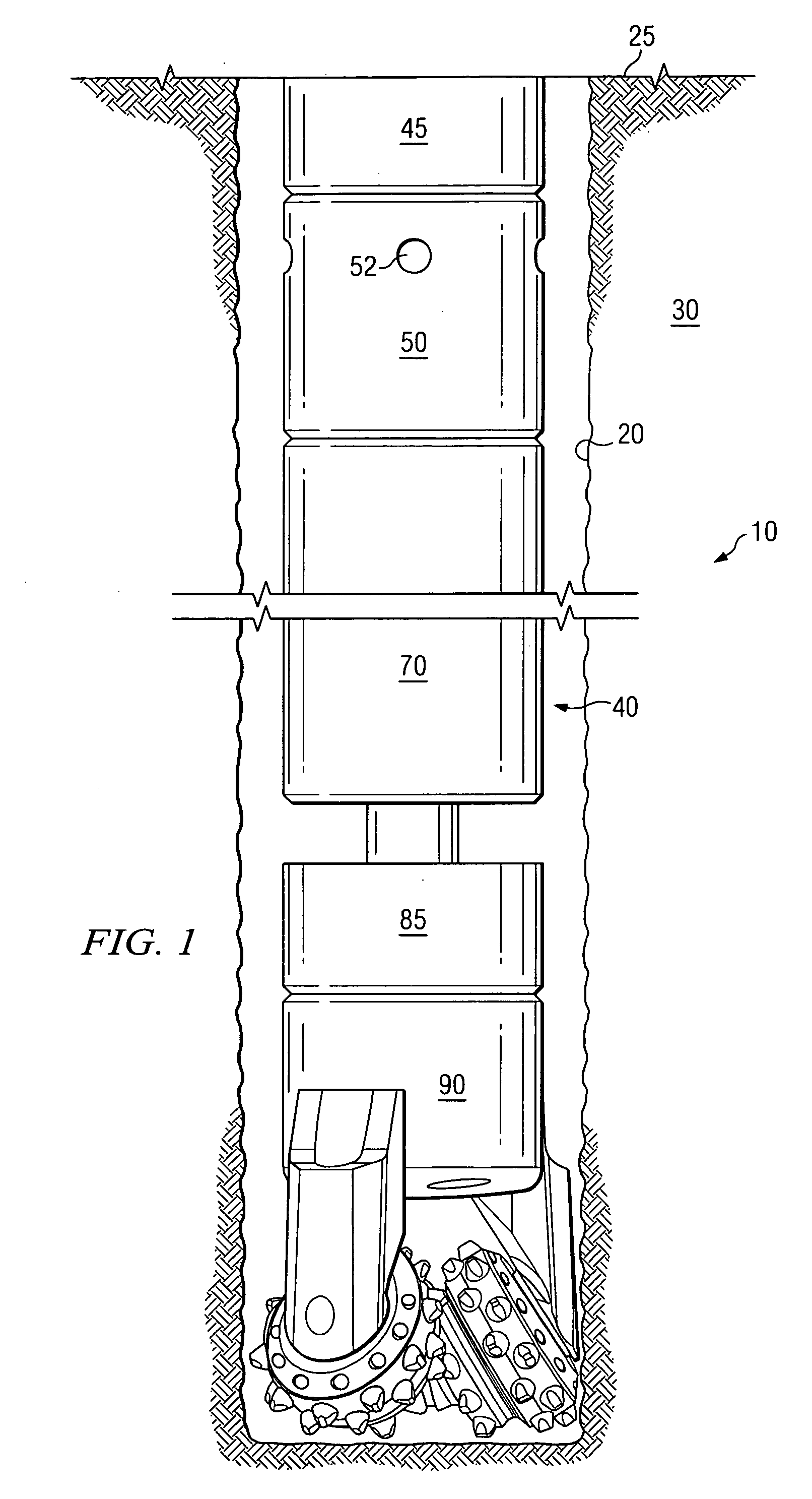
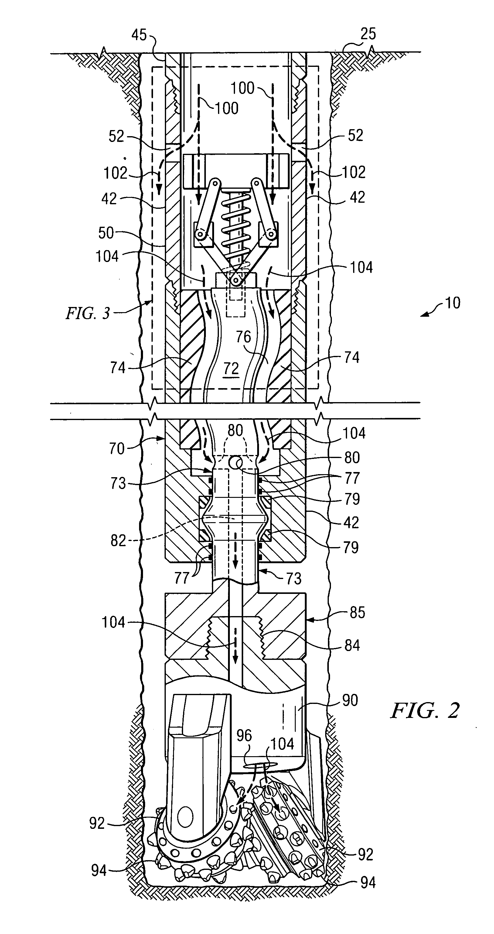
[0011]FIG. 1 illustrates an example system 10 for controlling drill motor rotational speed. In certain embodiments, system 10 may be used in a well bore 20 extending from surface 25 to penetrate a subterranean zone 30. Although FIG. 1 illustrates a substantially vertical well bore 20, system 10 may be implemented in articulated wells, slant wells, or any other types of wells or well systems. Subterranean zone 30 may comprise an oil or gas reservoir, a coal seam, or any other appropriate subterranean zone. Subterranean zone 30 may be accessed to remove and / or produce water, hydrocarbons, and other fluids in subterranean zone 30, to treat minerals in subterranean zone 30 prior to mining operations, or for any other suitable purpose.

[0012] System 10 includes a drill string 40 used to form well bore 20. In certain embodiments, drill string 40 includes a drill pipe 45, a motor governor 50, a downhole motor 70, a bit box 85, and a drill bit 90. Drill pipe 45 couples to motor governor 50 ...


PUM


Abstract

In one embodiment, a system for controlling drill motor rotational speed includes a downhole motor disposed in a drill string and having a rotor operable to be rotated by a flow of drilling fluid through the motor. The system also includes one or more by-pass ports operable to allow a portion of the drilling fluid to exit the drill string into a well bore and a governor coupled to the rotor and comprising a valve operable to move in response to the rotational speed of the rotor. The valve movement controls the amount of drilling fluid allowed to flow through the by-pass ports and exit the drill string into the well bore. The valve also directly controls the flow of the drilling fluid into the motor based on the amount of drilling fluid allowed to flow through the by-pass ports, thereby controlling the rotational speed of the rotor.

Description

TECHNICAL FIELD OF THE INVENTION [0001] The present invention relates generally to systems and methods for drilling in subterranean zones and, more particularly, to a system and method for controlling drill motor rotational speed. BACKGROUND OF THE INVENTION [0002] Subterranean drilling operations can expose well bore drilling equipment to severe operating conditions, which may be detrimental to the operating life of the equipment. To maximize drilling efficiency, well bore drilling equipment may be designed to withstand exposure to severe operating conditions for an extended period of time. However, a drill motor's operating life can be substantially affected by exposure to rotational over-speed conditions caused by inconsistencies in the flow of drilling fluid used to power the drill motor. Therefore, it is desirable to prevent or reduce such over-speed conditions. SUMMARY OF THE INVENTION [0003] The present invention provides a system and method for controlling drill motor rotati...

Claims


Application Information

Patent Timeline
Patent Type & Authority Applications(United States)
IPC IPC(8): E21B4/02E21B21/10
CPCE21B21/103E21B4/02
Inventor ZUPANICK, JOSEPH A.
Owner EFFECTIVE EXPLORATION
Why Eureka
Try Eureka