Lifting device for a luggage compartment in an aircraft, as well as aircraft with a lifting device for a luggage compartment

a luggage compartment and lifting device technology, which is applied in the direction of dressing tables, transportation and packaging, aircraft crew accommodation, etc., can solve the problems of extraordinary load on the electrical system, high weight, and high cost of pneumatic power generation elements in aircraft, so as to reduce the load on the electrical system, high power, and limited weight

Active Publication Date: 2005-09-29
AIRBUS OPERATIONS GMBH
View PDF10 Cites 8 Cited by
  • Summary
  • Abstract
  • Description
  • Claims
  • Application Information

AI Technical Summary

Benefits of technology

[0007] To reduce these drawbacks, an electric motor with a lower power demand may be used and the remaining force for closure of the luggage compartment may be generated by means of a mechanical power generation element, especially a gas-filled spring. Such arrangements, however, are maintenance-intensive, because of the limited lifetime of the gas-filled springs.
[0008] An exemplary embodiment of the present invention may provide for a lifting device for a luggage compartment in an aircraft that is low-maintenance and reduces the load on the electrical system, as well as preferably has a limited weight and is user-friendly.
[0009] According to an exemplary embodiment of the present invention, the power generation element is an electrical power generation element, and the lifting device has a rechargeable energy accumulator to store energy for operation of the electrical power generation element. Owing to the use of an electrical power generation element, maintenance-intensive mechanical power generation devices, especially gas-filled springs, can be dispensed with. The high power required to close the luggage compartment over a short time can be taken from the energy accumulator without loading the electrical system. The energy accumulator can preferably be recharged via the electrical system after removal of the electrical power.
[0010] The energy accumulator is preferably charged from the electrical system of a relatively longer period with a reduced charge power or current intensity, so that the load on the electrical system is reduced. Because of the smaller charge current intensity, the connection lines between the lifting device and the electrical system can have a small cross section and therefore low weight. To charge the energy accumulator with power from the electrical system, the lifting device expediently has a corresponding charging device. The charging power of the charging device is preferably much lower than the power demand of the electrical power generation device. “Much smaller” means at least by a factor of 2, preferably smaller by at least a factor of 5.
[0011] The weight force support is preferably exclusively electric. The electrical power generation device allows the luggage compartment to be fully closed without outside force support, which increases user friendliness.
[0012] Preferably, each luggage compartment of an aircraft has its own energy accumulator. A number of decentralized energy accumulators is therefore involved. This makes it possible to keep the line length laid out for high current intensity as limited as possible. It can also be expedient for a certain number of luggage compartments to provide a common energy accumulator, in order to reduce the number of energy accumulators.

Problems solved by technology

In addition, such arrangements, because of the limited lifetime of gas-filled springs, are maintenance-intensive.
Pneumatic power generation elements require costly devices for compressed air generation in the aircraft.
With the number of luggage compartments provided in an aircraft, this can lead to extraordinary loading of the electrical system at times. The supply lines from the electrical system to the electric motors must be laid out for high current intensities and therefore have high weight.

Method used


Image

  • Lifting device for a luggage compartment in an aircraft, as well as aircraft with a lifting device for a luggage compartment
  • Lifting device for a luggage compartment in an aircraft, as well as aircraft with a lifting device for a luggage compartment
  • Lifting device for a luggage compartment in an aircraft, as well as aircraft with a lifting device for a luggage compartment

Examples


Embodiment Construction

[0015] Other advantageous features are apparent from the following explanation of the invention by means of preferred variants with reference to the appended figures. In the figures:

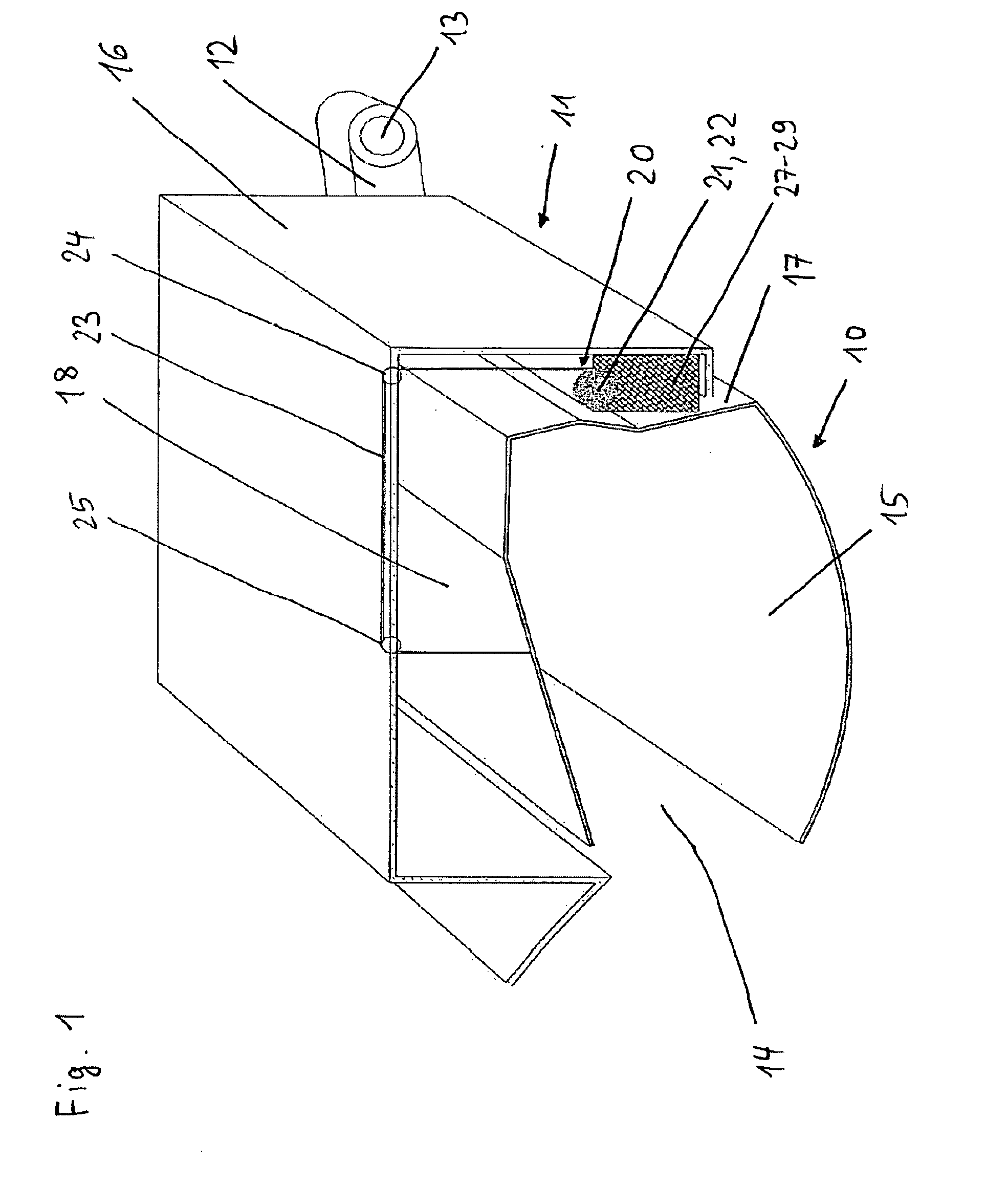
[0016]FIG. 1: shows a perspective view of a luggage compartment in the open state;

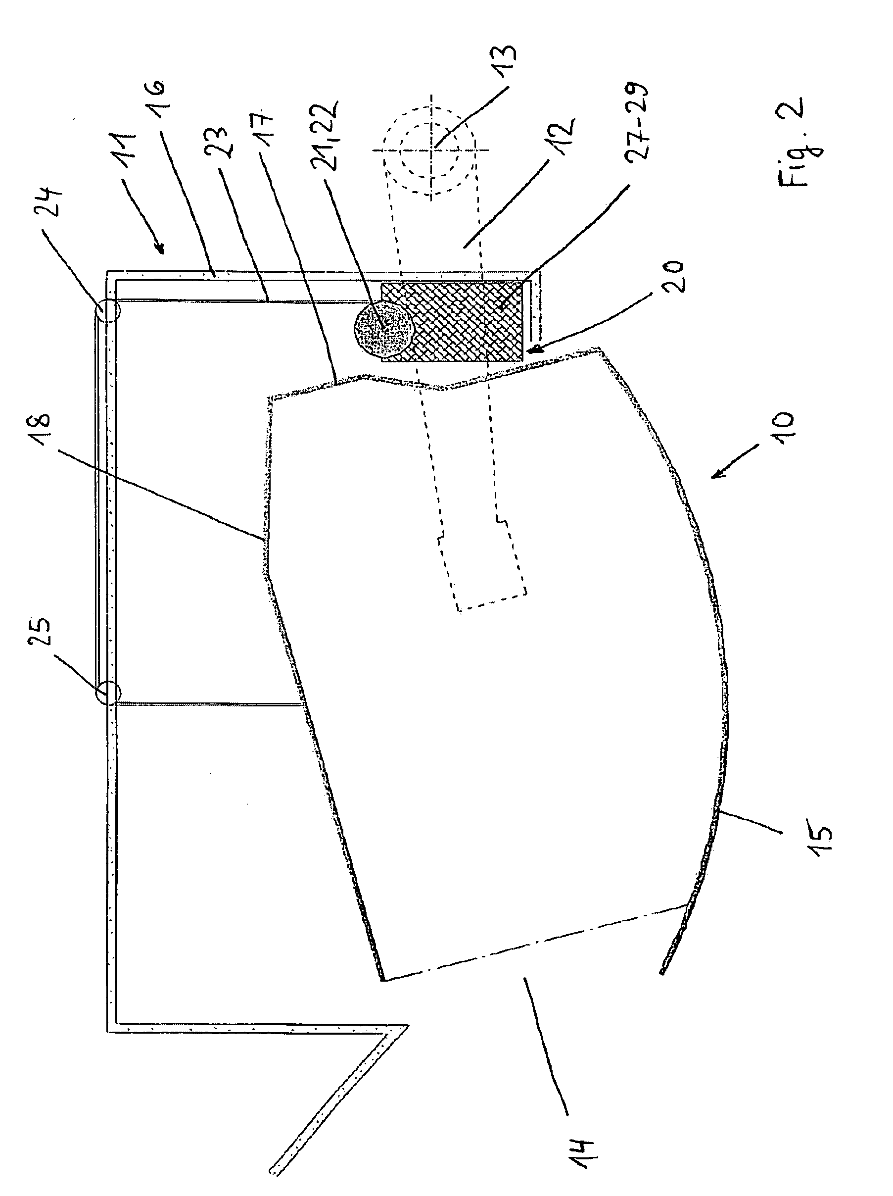
[0017]FIG. 2: shows a cross-sectional view of a luggage compartment in the open state;

[0018]FIG. 3: shows a cross-sectional view of a luggage compartment in the closed state; and

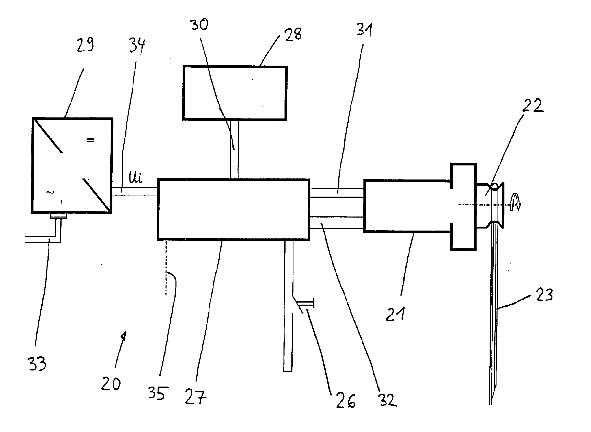
[0019]FIG. 4: shows a schematic view of a lifting device.

[0020] Luggage compartments are arranged in a longitudinal frame 11 above the rows of seats of an aircraft. A luggage compartment 10 is arranged pivotable by means of a support arm 12 relative to longitudinal frame 11 around hinge 13. In the open position depicted in FIGS. 1 and 2, the luggage compartment 10 can be loaded and unloaded through opening 14. In the closed position depicted in FIG. 3, the bottom wall 15 of luggage compartment 10 is sealed off flush with the longitudinal frame 1...


PUM


Abstract

The application concerns a lifting device for a luggage compartment in an aircraft, wherein the luggage compartment can be moved between an open and closed position, and the lifting device includes a power generation element that exerts a lifting force on the luggage compartment. The application also concerns an aircraft with a lifting device for a luggage compartment. The power generation element is an electrical power generation element, and the lifting device has a rechargeable energy accumulator to store energy for operation of the electrical power generation element.

Description

TECHNOLOGICAL BACKGROUND [0001] DE 41 30 644 and U.S. Pat. No. 5,567,028 describe a luggage compartment with opening aids.FIELD OF THE INVENTION [0002] The invention relates to a lifting device for a luggage compartment in an aircraft. SUMMARY OF THE INVENTION [0003] According to an exemplary embodiment, the luggage compartment can be moved between an opened and closed position, and the lifting device includes a power generation element that exerts a lifting force on the luggage compartment. The invention also concerns an aircraft with a lifting device for a luggage compartment. [0004] The invention, in particular, concerns movable luggage compartments arranged in commercial aircraft above the rows of seats. To move a luggage compartment from an open position to a closed position, a mechanical power generation element that supports the luggage compartment can be provided to assist the user, especially a gas-filled spring (DE 41 30 644 C2, U.S. Pat. No. 5,567,028). However, the requi...

Claims


Application Information

Patent Timeline
Patent Type & Authority Applications(United States)
IPC IPC(8): B60R5/00B61D37/00B64D11/00
CPCB64D11/003B60R5/003
Inventor WISCH, BODOROWOLD, LARS
Owner AIRBUS OPERATIONS GMBH
Why Eureka
Try Eureka