
Connector apparatus and method for connecting the same for controlling fluid dispensing

a technology of fluid couplers and connectors, applied in the direction of insulated cables, program control, special dispensing means, etc., can solve the problems of inability to distinguish, conventional female couplers, and inability to distinguish, so as to prevent mismatching, prevent misconnection, and reduce power

Inactive Publication Date: 2005-09-29
COLDER PRODS
View PDF30 Cites 64 Cited by
  • Summary
  • Abstract
  • Description
  • Claims
  • Application Information

AI Technical Summary

Benefits of technology

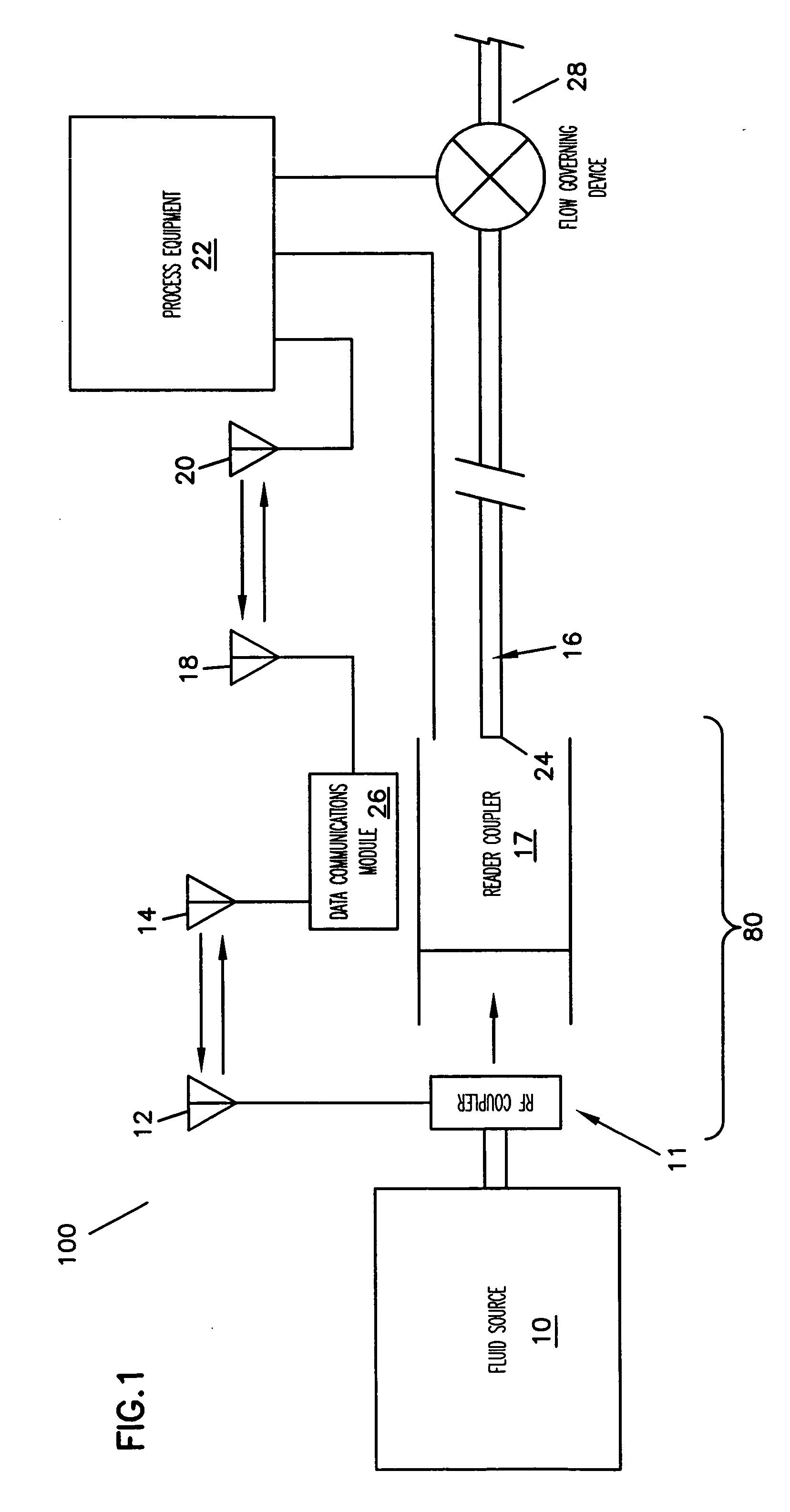
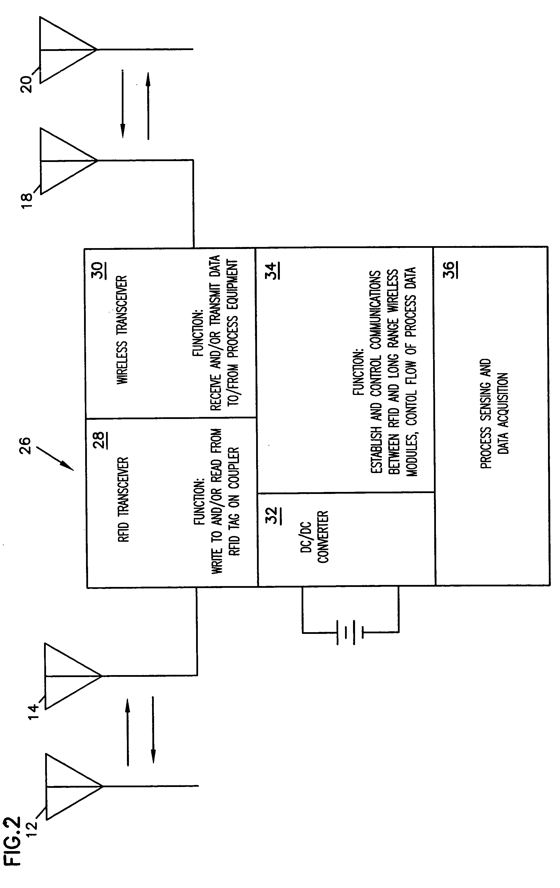
The invention is a connector apparatus that controls fluid dispensing and transmission. It includes a first coupler and a second coupler that are connected together through a fluid transfer line. The couplers communicate wirelessly using RF technology. The first coupler has a first RF device, while the second coupler has a second RF device. The first and second RF devices communicate when the couplers are in close proximity. The connector apparatus also includes a process equipment that is connected to the second coupler and can control fluid flow through the couplers. The process equipment can communicate with the first and second couplers through the RF devices. The connector apparatus allows for easy connection and control of fluid dispensing and transmission.

Problems solved by technology

However, these fluid connectors cannot distinguish one mating coupler from another.
The conventional female coupler, for example, cannot distinguish between mating male couplers that are unique with respect to the date and / or origin of manufacture, fluid compatibility, ownership, that are proprietary, or any other characteristic pertinent to the control of fluid flow through connectors.
Further, such fluid connectors do not provide a reliable structure and configuration for communication between the coupling halves in recognizing a positive connection therebetween within a desired range and for subsequent communication to control fluid flow.
Furthermore, existing devices do not provide a way to prevent misconnection between mismatched coupling halves in preventing product contamination.

Method used


Image

  • Connector apparatus and method for connecting the same for controlling fluid dispensing
  • Connector apparatus and method for connecting the same for controlling fluid dispensing
  • Connector apparatus and method for connecting the same for controlling fluid dispensing

Examples


Embodiment Construction

[0036] In the following description of the specific embodiments, reference is made to the accompanying drawings which form a part hereof, and in which is shown by way of illustration the specific embodiments in which the invention may be practiced. It is to be understood that other embodiments may be utilized as changes may be made without departing from the scope of the present invention.

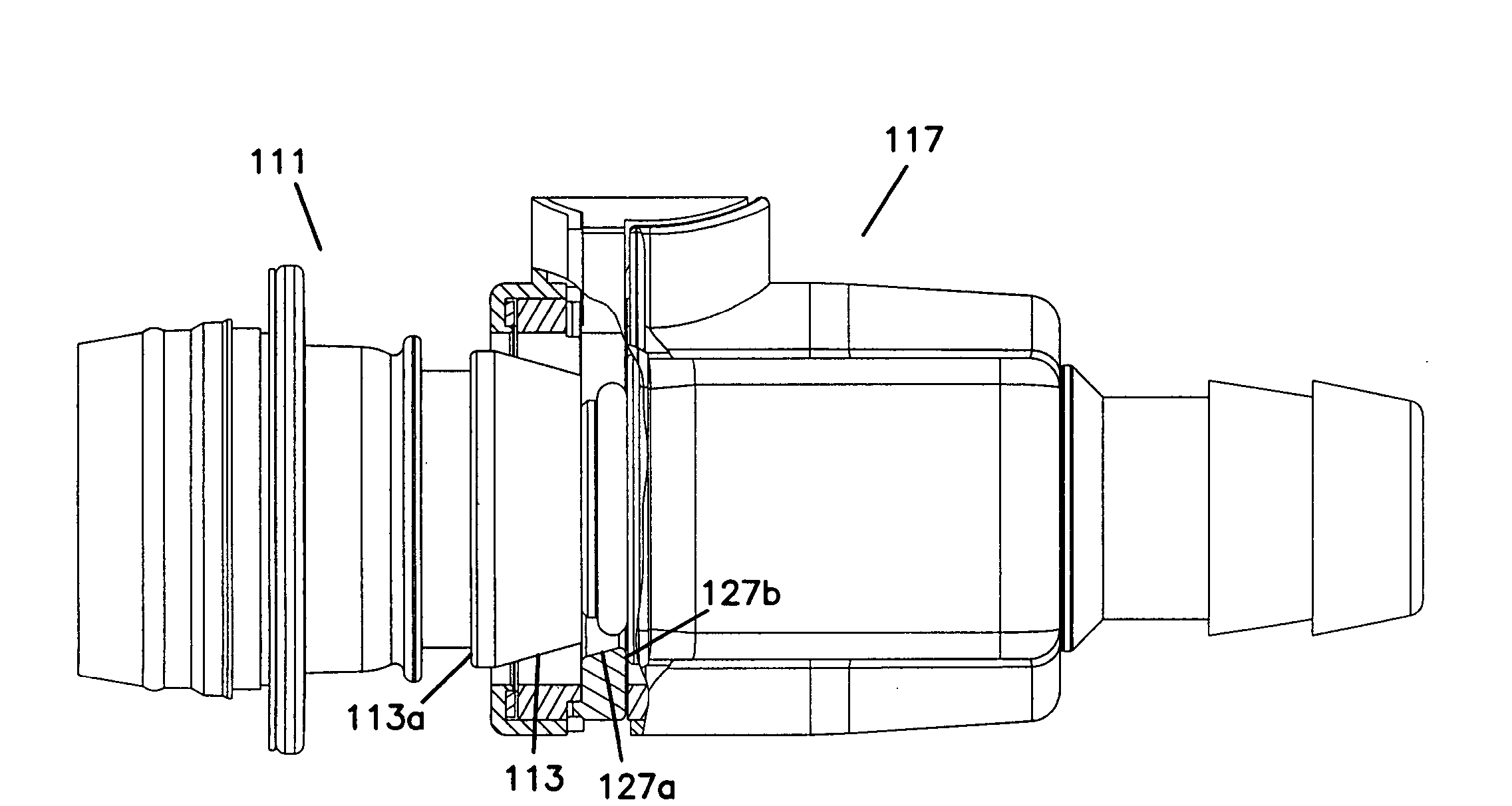
[0037] This invention provides a connector apparatus with an incorporated control component (i.e., transmitter components used therein) for controlling connection between coupling halves of the connector apparatus and for controlling fluid dispensing and transmission through the connector apparatus. Preferably, the transmitters communicate through wireless means. It will be appreciated the connector apparatus may be incorporated with a fluid source and fluid line for fluid dispensing in a fluid dispensing system or incorporated along a fluid transfer line.

[0038] Referring now to the drawings, FIG...


PUM

PropertyMeasurementUnit
operating frequencyaaaaaaaaaa
distanceaaaaaaaaaa
distanceaaaaaaaaaa

Abstract

A connector apparatus for controlling fluid dispensing / transmission that includes a control component for communication between couplers thereof. A first coupler has a transmitter, and is releasably connected with a mating reader coupler that has a transmitter and fluid control device to exchange information with the transmitter of the first coupler. The transmitters communicate and are operated by wireless means such as by RF devices. Upon confirming that the first coupler is properly coupled to the mating coupler and that the first coupler has a proper identification, the fluid control device controls fluid flow, using the transmitters of the first coupler and the mating reader coupler, under predetermined parameters, e.g., pressure, temperature, duration, and flow rate, as indicated in the first coupler.

Description

[0001] This application claims the benefit of U.S. Provisional Application Ser. No. 60 / 292,477, filed on May 21, 2001, entitled CONTROL SYSTEM HAVING RF COUPLER AND METHOD THEREOF, which is in its entirety incorporated herewith by reference.FIELD OF INVENTION [0002] The present invention relates to a connector apparatus and method for connecting a fluid coupler set for controlling fluid dispensing and fluid transmission. More specifically, the present invention relates to a Radio Frequency (RF) control system incorporated with a connector apparatus having a fluid coupler set with radio-frequency-identification (RFID) circuitry for monitoring and / or controlling fluid dispensing and fluid transmission. BACKGROUND OF THE INVENTION [0003] Typically, conventional fluid connectors used for fluid dispensing or fluid transmission have a fluid coupling assembly with a first end connected to a fluid source and a second end connected to a fluid system including a fluid line. The coupling assem...

Claims


Application Information

Patent Timeline
Patent Type & Authority Applications(United States)
IPC IPC(8): F16L25/00B67D7/34F16K31/02F16L37/098F16L37/12G06K19/00H04B1/59
CPCB67D7/348F16L2201/60F16L2201/10F16L37/0841Y10T137/3021B67D7/34
Inventor GARBER, RICHARD STEWARTDECLER, CHARLES PETERMEYER, DAVID W.
Owner COLDER PRODS
Learn More