Air cooling generator

a generator and air cooling technology, applied in the direction of machines/engines, electric motor propulsion transmissions, transportation and packaging, etc., can solve problems such as danger to users, and achieve the effect of reducing noise and great heat dissipation

Inactive Publication Date: 2005-09-29
WANG WEN CHANG
View PDF12 Cites 12 Cited by
  • Summary
  • Abstract
  • Description
  • Claims
  • Application Information

AI Technical Summary

Benefits of technology

[0006] The primary objective of the present invention is to provide a g...

Problems solved by technology

Thus, when the cooling fan is inoperative or worn out during a long-term utilization, the engine 120 continues to operat...

Method used


Image

  • Air cooling generator
  • Air cooling generator
  • Air cooling generator

Examples


Embodiment Construction

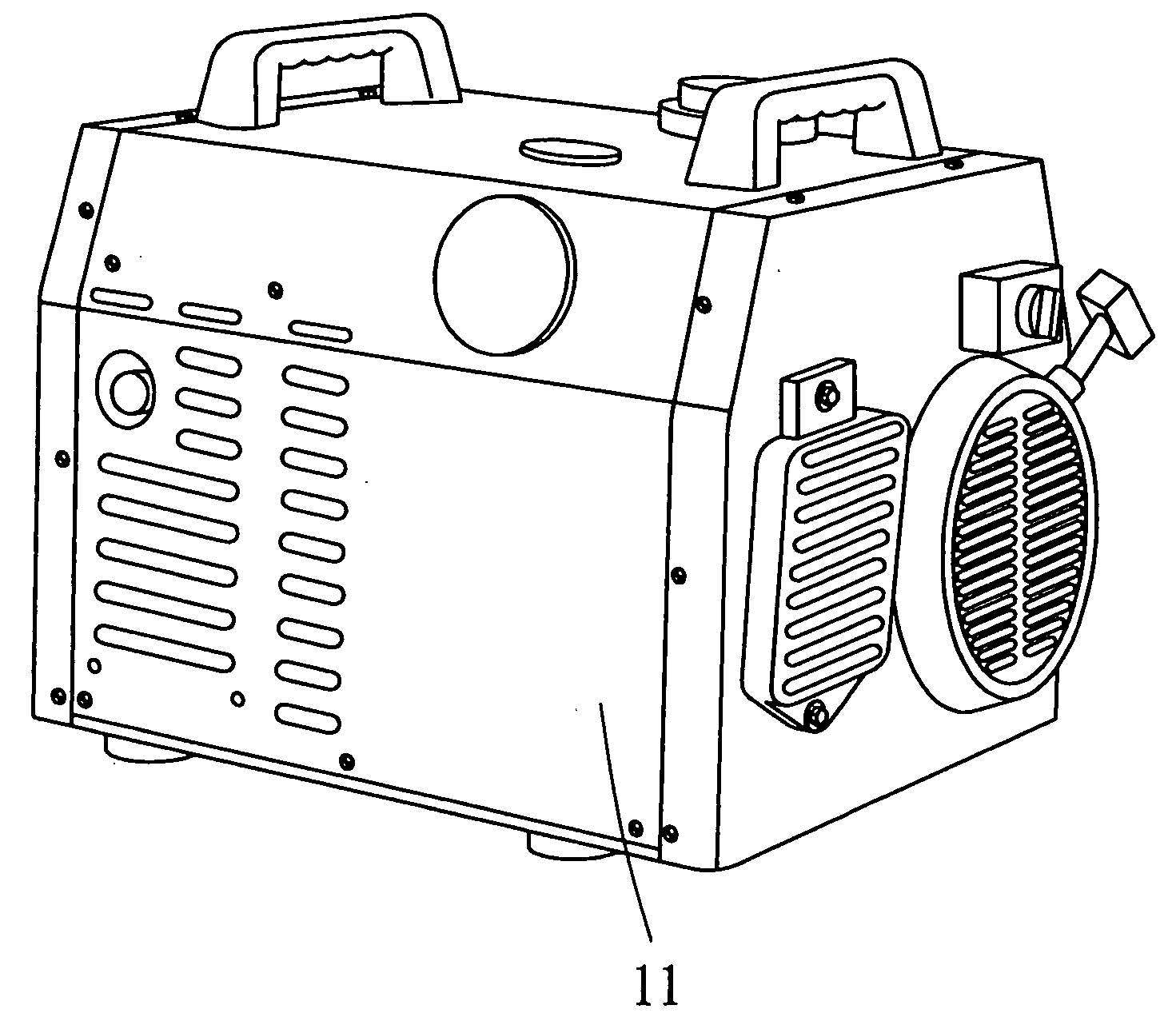
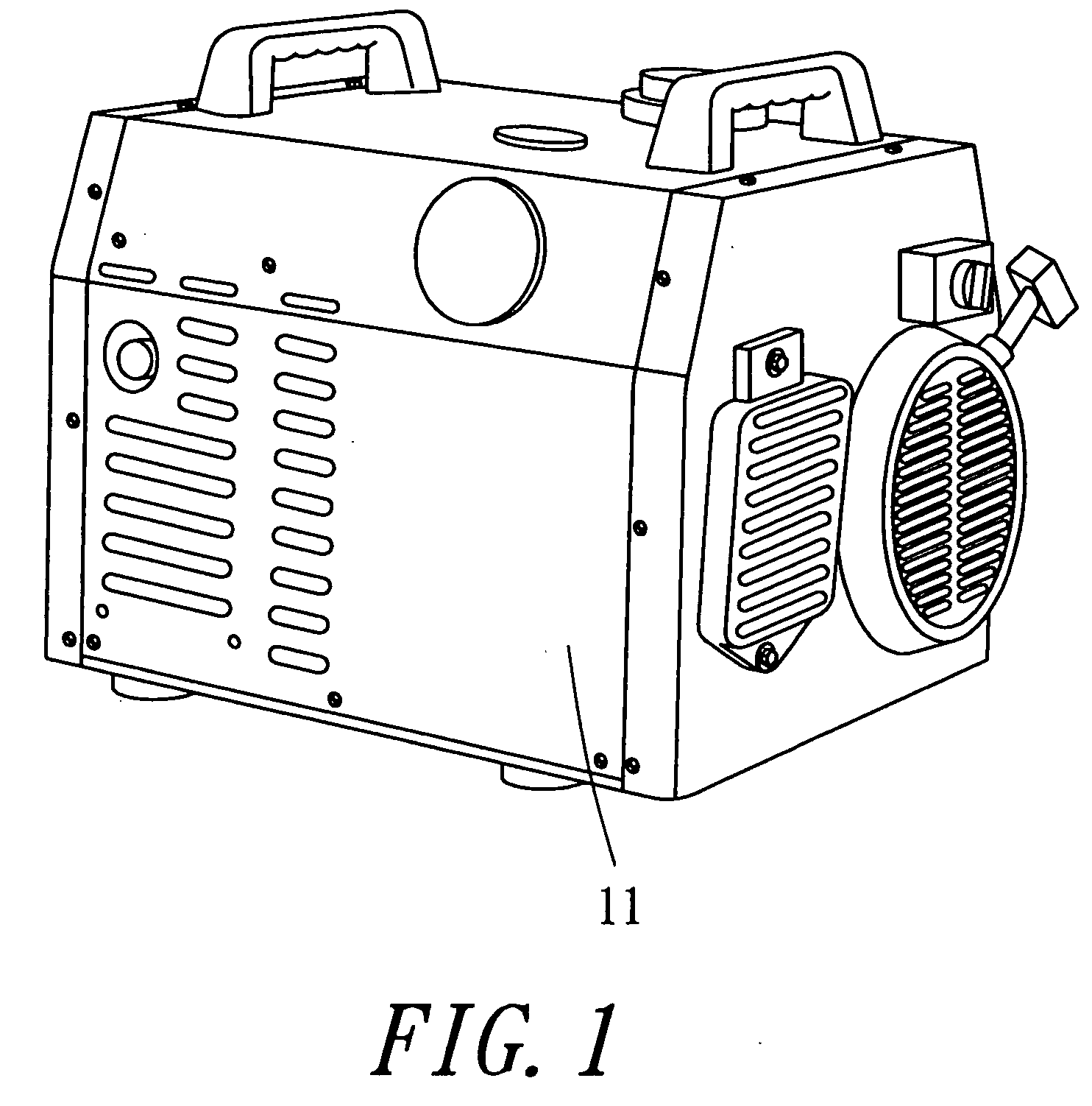
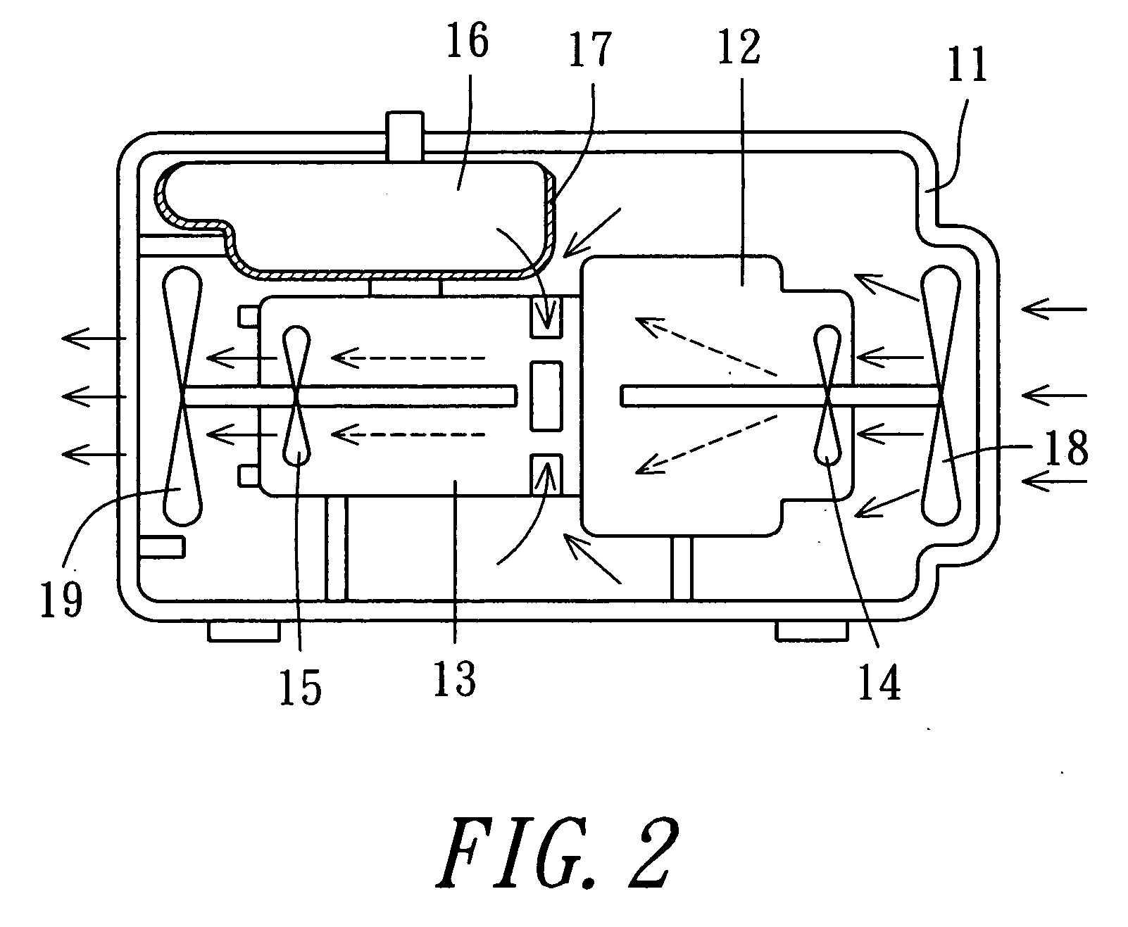
[0024] Referring to FIGS. 1 and 2, an air cooling generator in accordance with the preferred embodiment of the present invention comprises a housing 11, an engine 12 mounted in the housing 11, a first main impeller 14 rotatably mounted in the engine 12, a first secondary impeller 18 rotatably mounted in the housing 11 and located outside of the engine 12, a generating body 13 mounted in the housing 11 and connected to the engine 12, a second main impeller 15 rotatably mounted in the generating body 13, a second secondary impeller 19 rotatably mounted in the housing 11 and located outside of the generating body 13, an oil tank 16 mounted in the housing 11, and an insulating layer 17 mounted on a periphery of the oil tank 16.

[0025] Preferably, the first secondary impeller 18 is co-axial with the first main impeller 14 and has a size greater than that of the first main impeller 14, and the second secondary impeller 19 is co-axial with the second main impeller 15 and has a size greater...


PUM


Abstract

A generator includes a housing, an engine, a first main impeller rotatably mounted in the engine, a first secondary impeller rotatably mounted in the housing and located outside of the engine, a generating body, a second main impeller rotatably mounted in the generating body, and a second secondary impeller rotatably mounted in the housing and located outside of the generating body. Thus, the first secondary impeller and the second secondary impeller can dissipate the heat produced from the engine and the generating body, thereby enhancing the heat dissipation effect of the generator, and thereby increasing the lifetime of the generator.

Description

BACKGROUND OF THE INVENTION [0001] 1. Field of the Invention [0002] The present invention relates to an air cooling cab-type generator, and more particularly to a generator having a greater heat dissipation effect. [0003] 2. Description of the Related Art [0004] A conventional air cooling generator in accordance with the prior art shown in FIG. 3 comprises a housing 110, an engine 120 mounted in the housing 110, a first impeller 140 rotatably mounted in the engine 120, a generating body 130 mounted in the housing 110, a second impeller 150 rotatably mounted in the generating body 130, an oil tank 160 mounted in the housing 110, and an insulating layer 170 mounted on a periphery of the oil tank 160. [0005] However, the engine 120 and the generating body 130 produce a larger heat during operation, so that it is necessary to provide a cooling fan located outside of the housing 110 to provide a heat dissipation effect. Thus, when the cooling fan is inoperative or worn out during a long-...

Claims


Application Information

Patent Timeline
IPC IPC(8): B60L50/10B61C9/38F01D11/00F01P1/06F01P5/02F03B11/00
CPCF01P5/02F01P1/06
Inventor WANG, WEN-CHANG
Owner WANG WEN CHANG
Why Eureka
Try Eureka