Station for self-propelled robot

a self-propelled robot and station technology, applied in the direction of automatic actuation, process and machine control, etc., can solve the problems of low availability factor and robot cannot move nor work, and achieve the effect of high availability factor

Inactive Publication Date: 2005-09-29
FUNAI ELECTRIC CO LTD
View PDF0 Cites 164 Cited by
  • Summary
  • Abstract
  • Description
  • Claims
  • Application Information

AI Technical Summary

Benefits of technology

[0010] An object of the invention is to provide a station for a self-propelled robot, and particul

Problems solved by technology

During the charging, however, the robot can neither move nor work, and thus

Method used


Image

  • Station for self-propelled robot
  • Station for self-propelled robot
  • Station for self-propelled robot

Examples


Embodiment Construction

[0052] Embodiments of the invention will now be described with reference to the drawings. As an example of a self-propelled robot, the following description will be given on a mobile work robot, which is a self-propelled cleaner having a moving unit for moving the cleaner itself as well as a cleaning function as a kind of a work function, although the work function is not restricted to the cleaning function.

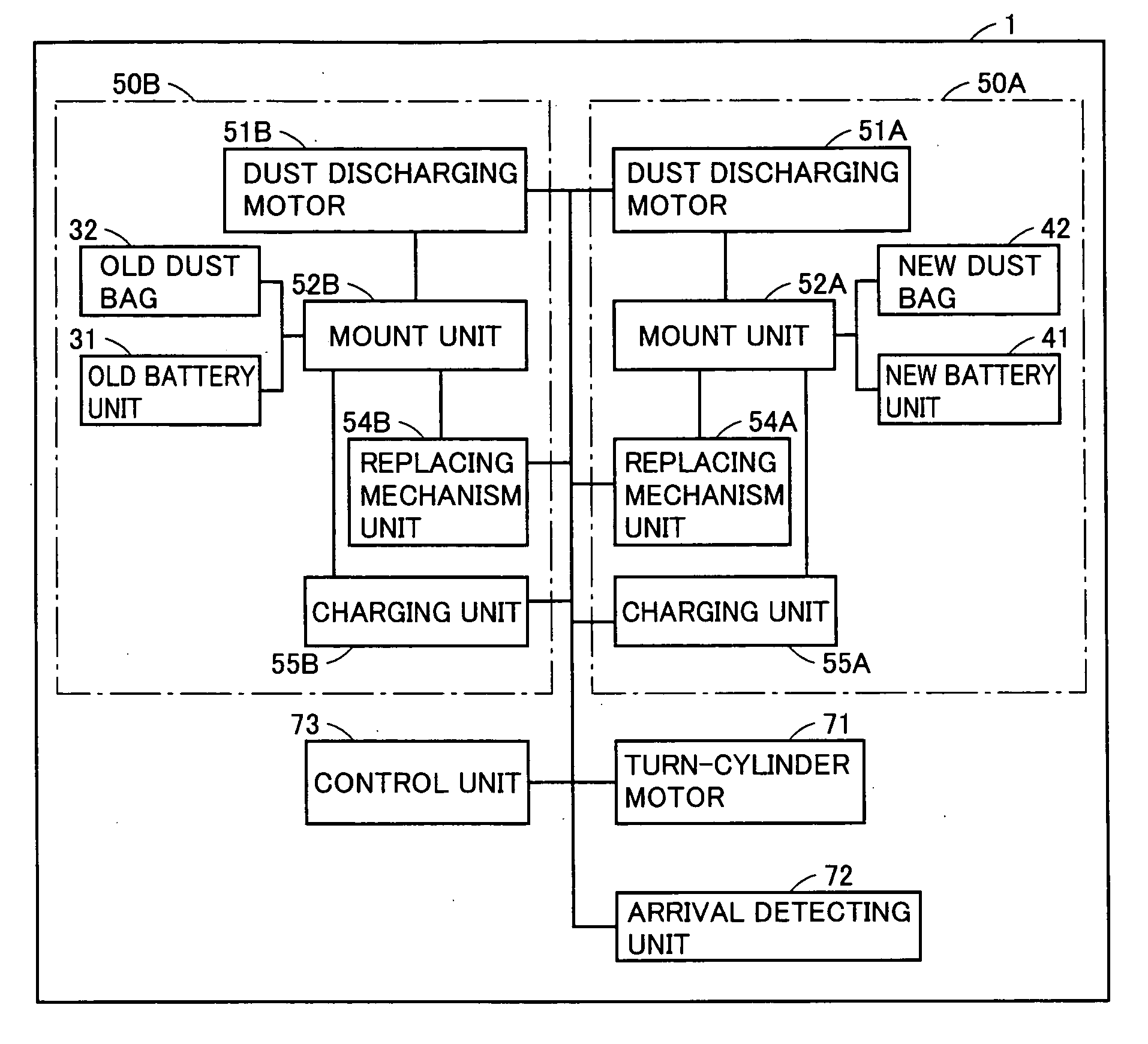
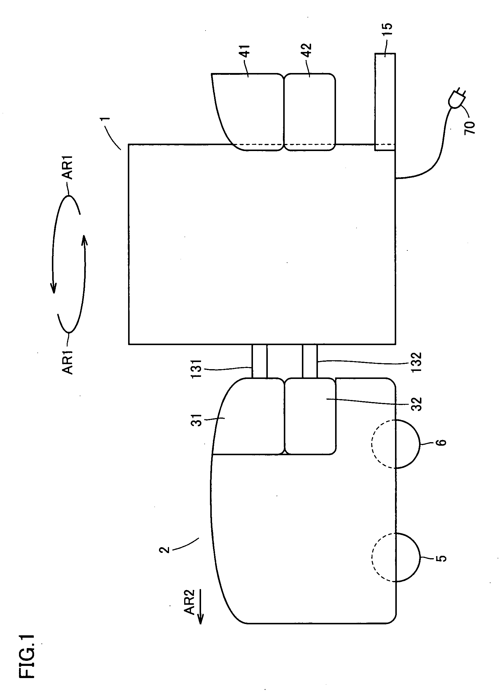
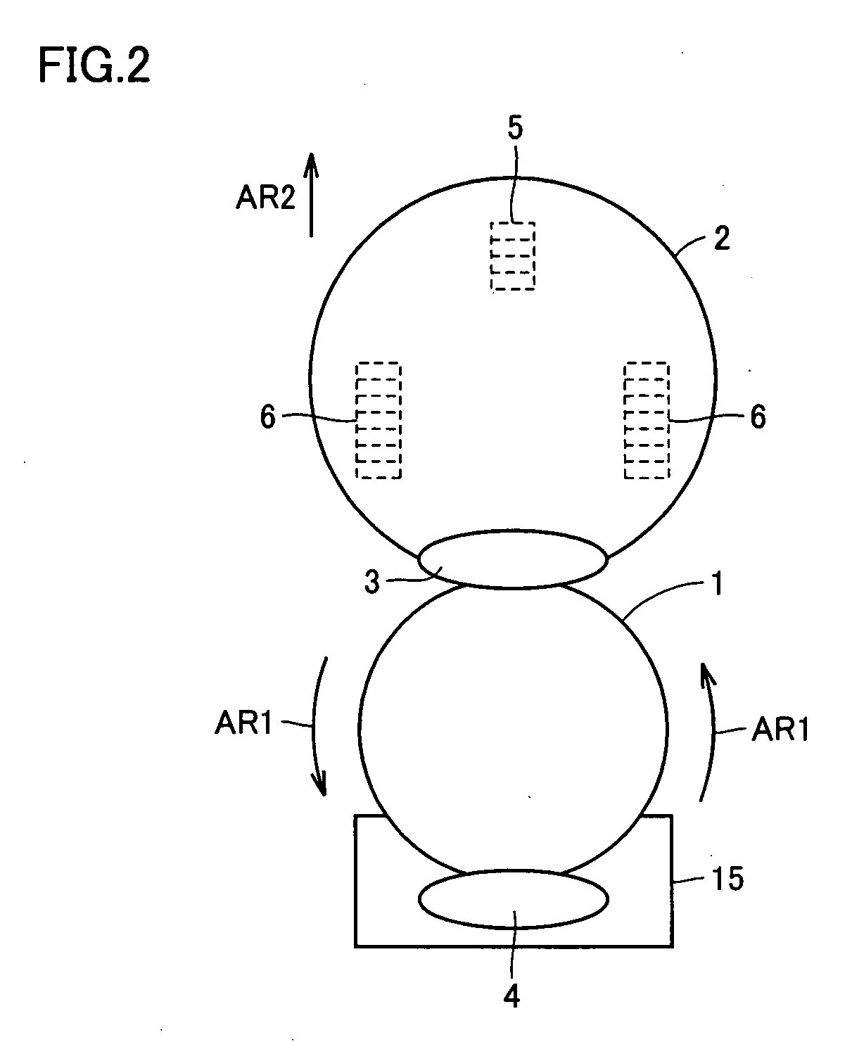
[0053] Referring to FIGS. 1 and 2, a mobile work robot system according to the embodiment includes a station 1 and one or more self-propelled cleaner 2. This system replaces an old battery unit 31 and an old dust bag 32 of self-propelled cleaner 2 with a new battery unit 41 and a new dust bag 42 without dust held on station 1. A function of this replacement will be described later with reference to FIG. 3.

[0054] Self-propelled cleaner 2 includes front and rear wheels 5 and 6 for a moving function. Station 1 has a function of charging old battery unit 31 replaced with new batter...


PUM


Abstract

A control unit of a station concentrically rotates a plurality of unit replacing units by a motor on a first horizontal plane parallel to a floor bearing the station when arrival of the self-propelled cleaner is detected. The control unit activates, as a unit for removing an old battery unit from the self-propelled cleaner, the unit replacing unit included among the plurality of unit replacing units and opposed to the self-propelled cleaner located on the station. After the old battery unit is removed from the self-propelled cleaner, the control unit activates the motor. By the rotation of this motor, another unit replacing unit opposed to the self-propelled cleaner is activated as a unit for attaching a new battery unit to the self-propelled cleaner instead of the unit replacing unit previously activated as the removing unit.

Description

BACKGROUND OF THE INVENTION [0001] 1. Field of the Invention [0002] The present invention relates to a station for a self-propelled robot, and particularly to a station having a function of charging a battery for the self-propelled robot. [0003] 2. Description of the Background Art [0004] In mobile work robots having a moving function for movement and a work function for cleaning or the like, power for driving primarily depend on internal batteries. Conventionally, charging of such batteries is performed manually, or is performed in such a manner that the mobile work robot moves to an independent station, and the battery is automatically charged by the station (see patent references 1-4). [0005] Patent Reference 1: Japanese Patent Gazette No. 2001-525567 [0006] Patent Reference 2: Japanese Patent Laying-Open No. 02-107219 [0007] Patent Reference 3: Japanese Patent Gazette No. 10-502274 [0008] Patent Reference 4: Japanese Patent Laying-Open No. 2002-345706 [0009] According to the tec...

Claims


Application Information

Patent Timeline
IPC IPC(8): A47L9/00A47L9/10A47L9/14A47L9/19A47L9/28B25J5/00G05D1/02H02J7/00
CPCA47L9/1481A47L9/19A47L9/2805A47L9/2852A47L9/2857A47L2201/022A47L9/2884G05D1/0225G05D1/0246G05D1/0255G05D2201/0203A47L9/2873
Inventor TAKENAKA, HIROYUKI
Owner FUNAI ELECTRIC CO LTD
Why Eureka
Try Eureka