Electric storage capacity estimation apparatus, method and program
Active Publication Date: 2020-09-17
KK TOSHIBA +1
View PDF0 Cites 2 Cited by
Summary
Abstract
Description
Claims
Application Information
AI Technical Summary
This helps you quickly interpret patents by identifying the three key elements:
Problems solved by technology
Method used
Benefits of technology
Benefits of technology
The invention provides a way to estimate the capacity of a storage battery in a large-scale electric storage system without stopping the operation of the system. This is done by using a current sensor to detect the electric current of the battery system and integrating it over time. The system can also estimate the state of deterioration of the battery over time by performing a regression analysis on the detected current. This enables the system to monitor the battery's performance in real-time and take necessary measures to maintain its efficiency and capacity.
Problems solved by technology
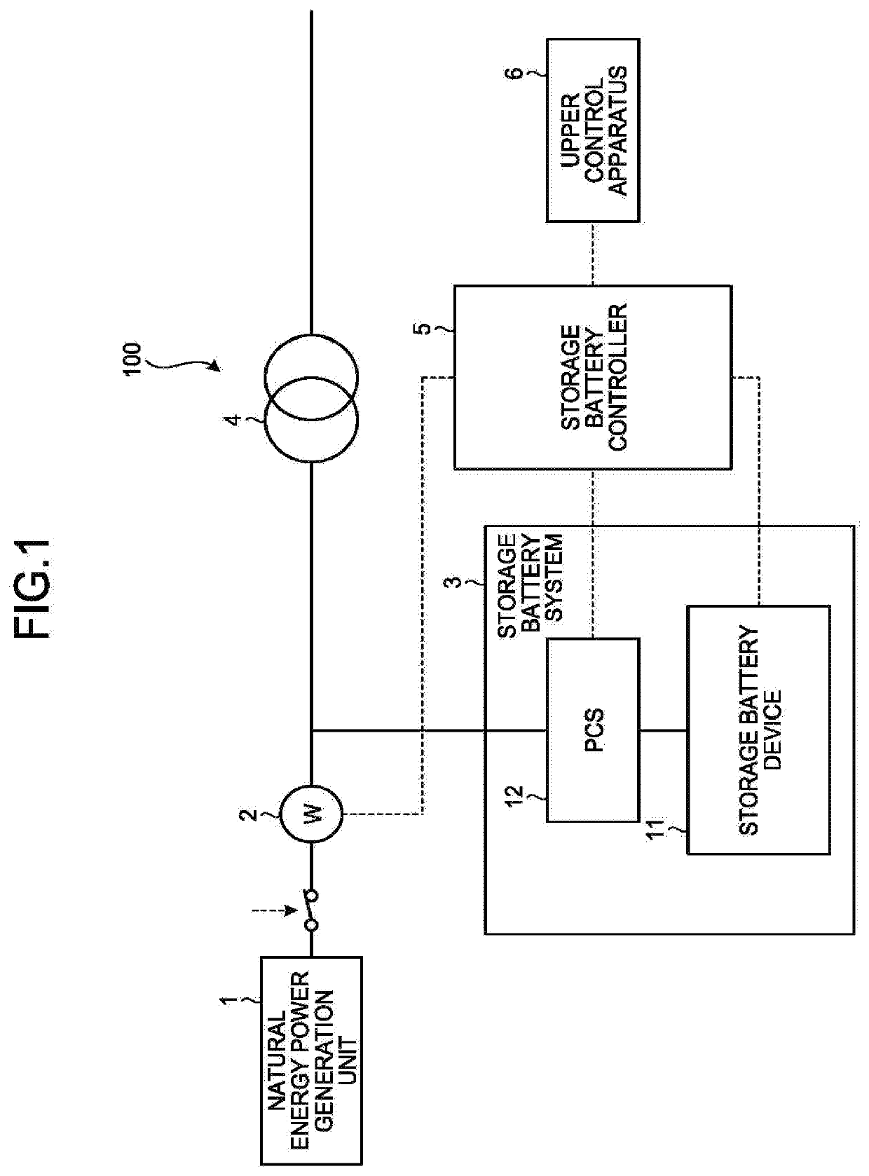
However, the power of the natural energy is unstable, and there is concern that the acceleration of extensive introduction of the natural energy causes adverse effects on the voltage and the frequency in an electric powersystem.
Furthermore, when the amount of supply of the natural energy extensively exceeds electric power demands, it is necessary to stop the natural energy power generation system thus lowering the utilization factor of power generation equipment.
Method used
Image
Click on the blue label to locate the original text in one second.
Reading with bidirectional positioning of images and text.
Examples
first embodiment
1. First Embodiment
[0078]Next, operation according to the first embodiment will be explained.
[0079]FIG. 6 is an operation flow chart according to the first embodiment.
[0080]FIG. 7 is an operation timing chart of the storage battery system according to the first embodiment.
[0081]The processing illustrated in FIG. 6 is, for example, processing installed in the EMU 36, the processing being performed as fixed-cycle processing (for every one second, for example). The following explanation is made assuming that the GMU 36 performs the processing.
[0082]In this case, at a time of power activation, initialization processing that resets a stabilization data matrix, each of flags, and each of the contents of counters to zero is performed.
[0083]The BMU 36 determines whether predetermined fluctuation occurs in the SOC of the storage battery systems 3 (Step S11 to Step S13).
[0084]To be more specific, the BMU 36 first determines whether the absolute value of the current integrated value ΣI from th...
second embodiment
2. Second Embodiment
[0128]Although in the first embodiment, the occurrence of the stabilization state or the non-stabilized state is detected to perform an estimation processing, the storage battery system is operated in a state that the SOC is set to a predetermined value (an average SOC is set to 50%, for example) depending on the system to be operated, and there exists the case that an SOC estimation processing is incapable of being accurately performed because the stabilization state or the non-stabilized state does not necessarily appear clearly in a normal operation state.
[0129]Accordingly, in the second embodiment, the transition between the stabilization state and the non-stabilized state is intentionally made thus performing accurately the SOC estimation processing.
[0130]The following explanation is made with respect to the case where in a system that is operated throughout the year and controlled so that the average SOC is set to 50% in a standby state, the SOC estimation ...
first modification
4.1. First Modification
[0161]It is possible to use Kaufman-filter SOC estimation processing as specific realization means of the SOC estimation processing based on cellvoltage data. The Kaufman-filter SOC estimation processing creates a model capable of simulating the voltage behavior of the cell to correct and converge the SOC value that is an internal parameter so that the voltage output cf the model and the measured cell voltage coincide with each other thus performing the SOC estimation processing.
PUM
Abstract
A battery capacityestimation apparatus includes one or more hardware processors that: calculate a current integrated value by integrating electric currents of a secondary battery system whose capacity is to be estimated; calculate an SOC estimate value in a stabilization state where a change in SOC of a secondary battery per unit time is comparatively small; perform a regression analysis in which the current integrated value is defined as a dependent variable and the SOC estimate value is defined as an independent variable, the regression analysis being performed while correcting the current integrated value based on a value of a coefficient of determination so that a result of the regression analysis has predetermined accuracy; and estimate a capacity of the secondary battery system based on the result of the regression analysis.
Description
FIELD[0001]The present invention relates to an electric storage capacity estimation apparatus, a method, and a program.BACKGROUND[0002]In recent years, the introduction of safe-and-clean natural energy, such as photovoltaic power generation, wind power generation, or the like, has been accelerated. However, the power of the natural energy is unstable, and there is concern that the acceleration of extensive introduction of the natural energy causes adverse effects on the voltage and the frequency in an electric powersystem. Furthermore, when the amount of supply of the natural energy extensively exceeds electric power demands, it is necessary to stop the natural energy power generation system thus lowering the utilization factor of power generation equipment.[0003]In order to solve those drawbacks, it is expected that a large-scale storage battery system that uses a secondary battery is provided to the power generation system so as to suppress the output fluctuation of the natural e...
Claims
Application Information
Patent Timeline
Application Date:The date an application was filed.
Publication Date:The date a patent or application was officially published.
First Publication Date:The earliest publication date of a patent with the same application number.
Issue Date:Publication date of the patent grant document.
PCT Entry Date:The Entry date of PCT National Phase.
Estimated Expiry Date:The statutory expiry date of a patent right according to the Patent Law, and it is the longest term of protection that the patent right can achieve without the termination of the patent right due to other reasons(Term extension factor has been taken into account ).
Invalid Date:Actual expiry date is based on effective date or publication date of legal transaction data of invalid patent.

