
Cylinder identification device for internal combustion engine

a technology for internal combustion engines and identification devices, which is applied in the direction of position/direction control, fuel injection apparatus, special data processing applications, etc., can solve the problems of delayed staring time of the engine, engine running for a while by inertia, and inability to conduct fuel injection, etc., to achieve enhanced engine startability

Inactive Publication Date: 2005-09-29
DENSO CORP
View PDF5 Cites 14 Cited by
  • Summary
  • Abstract
  • Description
  • Claims
  • Application Information

AI Technical Summary

Benefits of technology

[0006] The present invention is made in view of the foregoing matter and it is an object of the present invention to provide a cylinder identification device that can identify the initial cylinder in a short period, into which the fuel is initially injected at the time of the engine starting, whereby the startability of the engine is enhanced.

Problems solved by technology

Before the cylinder identification, fuel injection cannot be conducted, whereby a staring time of the engine is delayed.
The engine, however, runs for a while by the inertia thereof after an ignition switch is turned off to terminate ignitions and fuel injections.
Just before the engine stops completely, a piston in a compression stroke may hardly pass over the top dead center (TDC) by a compression pressure in the cylinder, which causes a reverse stroke of the piston, so that the precise detection of the stop position of the engine is hardly obtained.
Thus, even if the stop position of the engine is memorized, the initial cylinder into which the fuel is injected at the time of the engine starting may be misidentified due to the incorrectness of the memorized data, whereby a startability and an emission of the engine are deteriorated.

Method used


Image

  • Cylinder identification device for internal combustion engine
  • Cylinder identification device for internal combustion engine
  • Cylinder identification device for internal combustion engine

Examples


Embodiment Construction

[0018] An embodiment of the present invention will be described hereinafter with reference to the drawings.

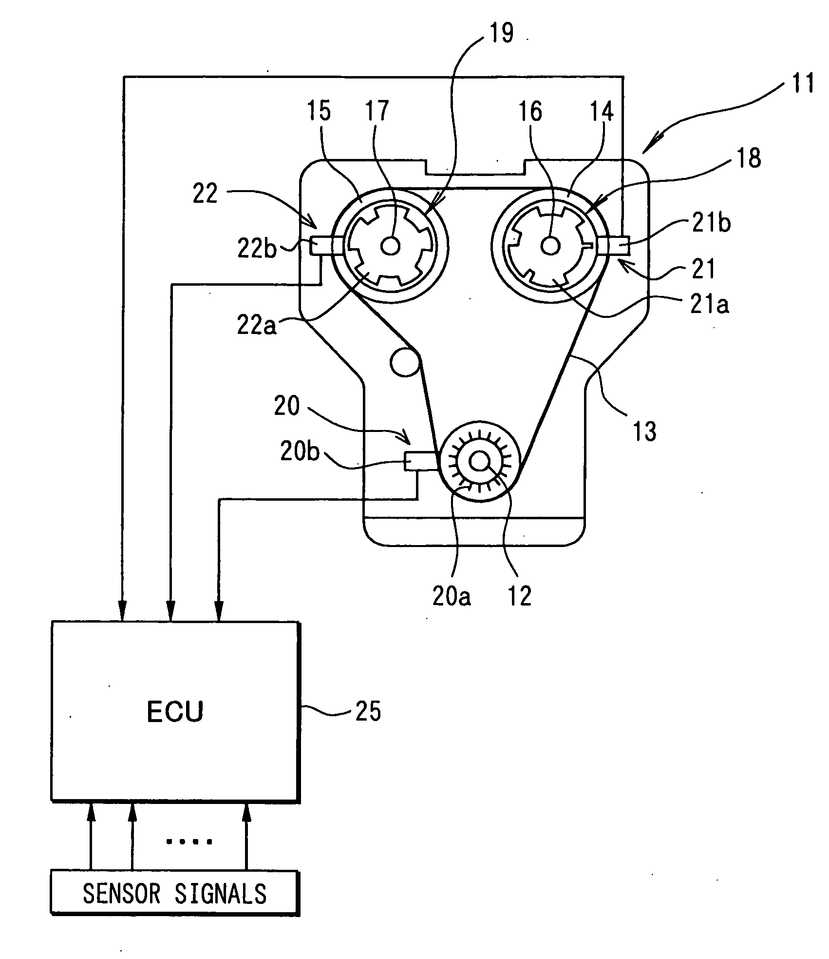
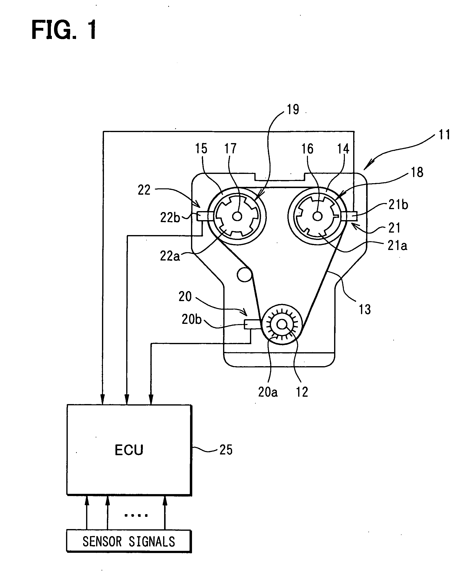
[0019] Referring to FIG. 1, a driving force of an engine 11 is transferred from a crankshaft 12 to an intake camshaft 16 and an exhaust camshaft 17 through a timing chain 13 and sprockets 14, 15.

[0020] The intake camshaft 16 and the exhaust camshaft 17 are respectively provided with valve timing controllers 18, 19, which adjust opening / closing timing of an intake and an exhaust valve (not shown) by varying a rotational phase of the camshafts 16, 17 relative to the crankshaft 12.

[0021] The crankshaft 12 is provided with a crank sensor 20, which includes a crank rotor 20a rotating with the crankshaft 12 and a sensor portion 20b fixed on a predetermined position. The crank rotor 20a has teeth at an outer circumferential surface thereof, which are arranged at uniform intervals of a predetermined crank angle, for example, 6° C.A. The crank rotor 20a has a teeth-lacked portion tha...


PUM


Abstract

A cylinder identification device has an intake cam sensor and an exhaust cam sensor which output signals indicative of a rotation angle of the camshaft. The levels of the output signals are varied according to the rotation angle of the crankshaft. The cylinder identification is conducted based on an order of combination variation of the output signal levels. The changing positions of the output signal levels of at least one of the intake cam sensor and the exhaust cam sensor are arranged in such a manner to correspond to positions or right before positions in which the fuel can be initially injected at the time of the engine starting. Thus, the cylinder identification device can identify the initial cylinder in a short period, into which the fuel is initially injected at the time of the engine starting, whereby the startability of the engine is enhanced.

Description

CROSS REFERENCE TO RELATED APPLICATIONS [0001] This application is based on and incorporates herein by reference Japanese Patent Application No. 2004-89462 filed on Mar. 25, 2004, the disclosure of which is incorporated herein by reference. FIELD OF THE INVENTION [0002] The present invention relates to a cylinder identification device for an internal combustion engine, the internal combustion engine equipped with an intake cam sensor and an exhaust cam sensor. BACKGROUND OF THE INVENTION [0003] Generally, an internal combustion engine for a vehicle, which is referred to as an engine hereinafter, is provided with a cam sensor which detects a reference position of a camshaft, and a crank sensor which outputs pulse signals indicative of a rotational position of the crankshaft. A cylinder identification is conducted based on the pulse signals, and a crank angle is detected based on the number of the pulse signals. Alternatively, a crank rotor of the crank sensor has a teeth-lacked porti...

Claims


Application Information

Patent Timeline
Patent Type & Authority Applications(United States)
IPC IPC(8): F02D35/00F02D41/06G01B21/00F02D45/00G01B7/14G01B21/22G01D5/249G01M15/00
CPCG01D5/2492
Inventor ASAMA, HIDEHIKO
Owner DENSO CORP
Learn More