Programmable frequency divider

a frequency divider and programming technology, applied in the field of frequency dividers, can solve the problems of increasing production costs, unfavorable capacitance load, and unfavorable signal division,

Active Publication Date: 2005-09-29
SILICON LAB INC
View PDF10 Cites 38 Cited by
  • Summary
  • Abstract
  • Description
  • Claims
  • Application Information

AI Technical Summary

Benefits of technology

[0005] An embodiment of the present invention provides a programmable frequency divider capable of applying any of multiple different divide ratios to an input signal. If necessary, the divider will self correct the duty cycle of its output to achieve a substantially 50 percent duty cycle. The frequency divider includes a sequence of divide stages, and at l

Problems solved by technology

A drawback of using multiple divider circuits in this way, however, is that undesired capacitive loads may be imposed on the signal being divided.
These undesired capacitance loads may be particularly troublesom

Method used


Image

  • Programmable frequency divider
  • Programmable frequency divider
  • Programmable frequency divider

Examples


Embodiment Construction

)

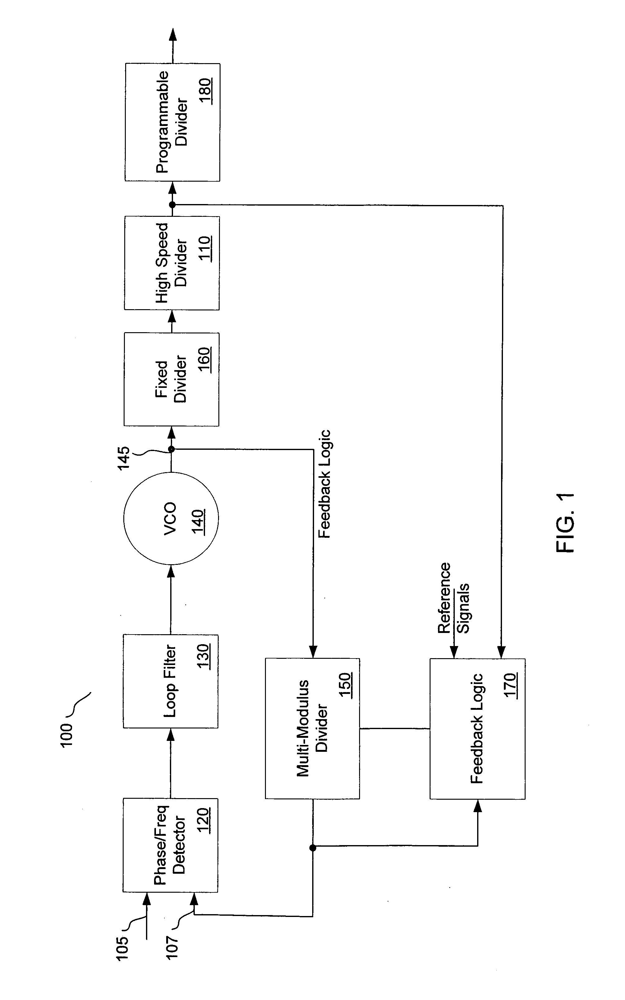
[0021] Referring first to FIG. 1, a phase-locked loop 100 having a dual feedback path structure, including a frequency divider such as high-speed divider 110, is illustrated according to an embodiment of the present invention. The phase-locked loop 100 includes phase / frequency detector (PFD) 120, which detects a phase difference between a clock signal at node 105 and a feedback signal at node 107. The output of the PFD 120 is provided to loop filter 130, which generates a voltage proportional to the phase / frequency difference detected by PFD 120. The voltage generated by low pass filter 130 is provided to voltage controlled oscillator 140 which generates an output signal at node 145. The frequency and phase of the signal at node 145 is dependent upon the phase difference between the input clock at node 105 and the feedback signal at node 107. Multi-modulus divider 150, which lies in the first feedback path of the phase-locked loop 100, divides the frequency of the signal at node 14...


PUM


Abstract

A divider is disclosed herein. The divider includes a sequence of divide stages programmably coupled to provide a variety of divide ratios. The divider also includes one or more multiplexers to feedback the output of a divide stage to the input of a divide stage earlier in the sequence of divide stages. The divider may also include duty cycle correction circuitry and self correction logic to correct abnormal logic states. The divide stages can operate in synchronism with each other. Multiplexer functionality, self correction circuitry functionality, and divide stage functionality may be implemented in a combination latch circuit.

Description

BACKGROUND [0001] 1. Field of the Invention [0002] This invention relates generally to frequency dividers, and more particularly to programmable frequency dividers. [0003] 2. Description of the Related Art [0004] Frequency dividers used in high speed circuits are often required to provide a variety of different output frequencies from a single input frequency. One method of providing these different frequencies involves using a number of individual divider circuits that each apply different divide ratios to the input signal. The output of one of the divider circuits is then selected to provide the final output. A drawback of using multiple divider circuits in this way, however, is that undesired capacitive loads may be imposed on the signal being divided. These undesired capacitance loads may be particularly troublesome when dealing with high frequency clock signals. Additionally, using multiple divider circuits may require additional power, and in some cases additional chip area, r...

Claims


Application Information

Patent Timeline
IPC IPC(8): H03K21/08H03K21/40H03K23/66
CPCH03K21/08H03K23/667H03K21/40
Inventor SUN, LIZHONGSIGNORE, BRUCE DELTHOMSEN, AXELPASTORELLO, DOUGLAS F.
Owner SILICON LAB INC
Why Eureka
Try Eureka