Print head

a printing head and print head technology, applied in the field of printing heads, can solve the problems of how the heat generated in the print head chips is to be dissipated, the ink leakage the heat emission of the print head, so as to achieve simple ambient dissipation and enhance the cooling effect

Inactive Publication Date: 2005-09-29
SONY CORP
View PDF3 Cites 5 Cited by
  • Summary
  • Abstract
  • Description
  • Claims
  • Application Information

AI Technical Summary

Benefits of technology

[0024] Accordingly, a first object of the present invention is to provide a print head for a line printer in which print head chips are arranged, wherein errors between the print head chips and another component are reduced and ink leakage is prevented without increasing the processing accuracy and the attachment accuracy of each component. In addition, a second object of the present invention is to provide a print head for a line printer in which print head chips are arranged, wherein heat generated in the print head chips is efficiently dissipated without making the structure complex or increasing the size of the print head.
[0034] In addition, since the ink-path member is continuously cooled due to the ink flow, the cooling effect can be enhanced compared to simple ambient dissipation.

Problems solved by technology

Accordingly, there is a risk in that ink will leak out of the print head 1 though these gaps.
On the other hand, in the above-described known technique, heat is emitted from the print head chips when they are driven, that is, when the heating elements are heated, and there is a problem as to how the heat generated in the print head chips is to be dissipated.
In particular, heat generation cannot be ignored in print heads for line printers since they include many print head chips and there are the same number of heat generators as the number of print head chips.
If the temperature exceeds this limit, a state in which a proper amount of ink is properly ejected cannot be obtained and the printing quality will be degraded.
However, this method has a problem in that the overall print speed is reduced if the stopping time is increased to suppress the temperature increase.
However, in the case in which the heat-dissipating member is installed in the print head, sufficient ambient dissipation cannot be provided unless the surface area of the heat-dissipating member is large.
Accordingly, there is a problem in that the size of the print head is increased if a large heat-dissipating member is installed.
On the contrary, if the surface area of the heat-dissipating member is reduced, sufficient ambient dissipation cannot be provided.
In addition, print head chips are generally arranged in a zigzag pattern in known print heads for line printers, and it is difficult to accurately process the heat-dissipating member in accordance the arrangement of the print head chips and install it.

Method used


Image

  • Print head
  • Print head
  • Print head

Examples


first embodiment

[0062] (First Embodiment)

[0063] A first embodiment achieves the above-described first object.

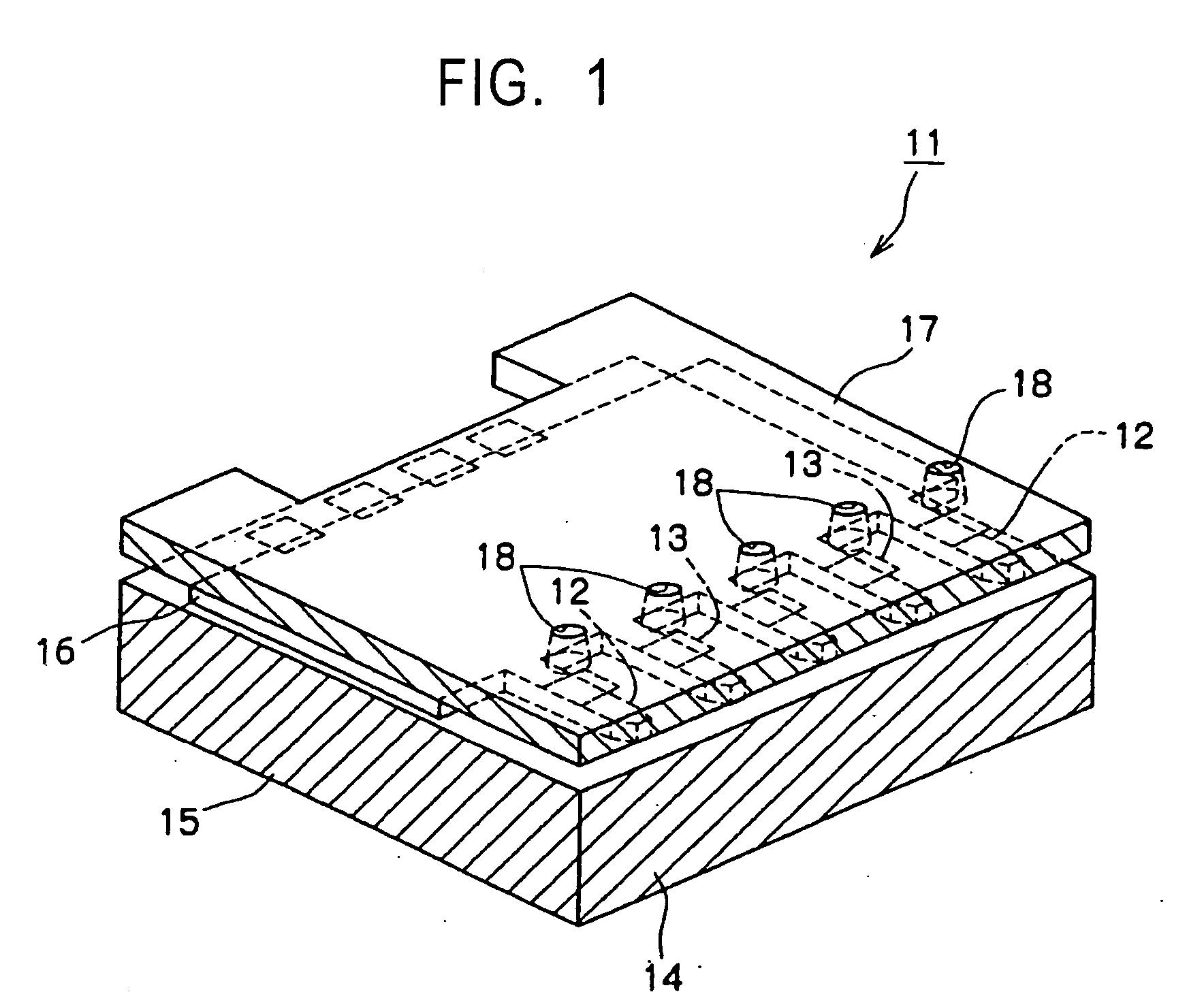
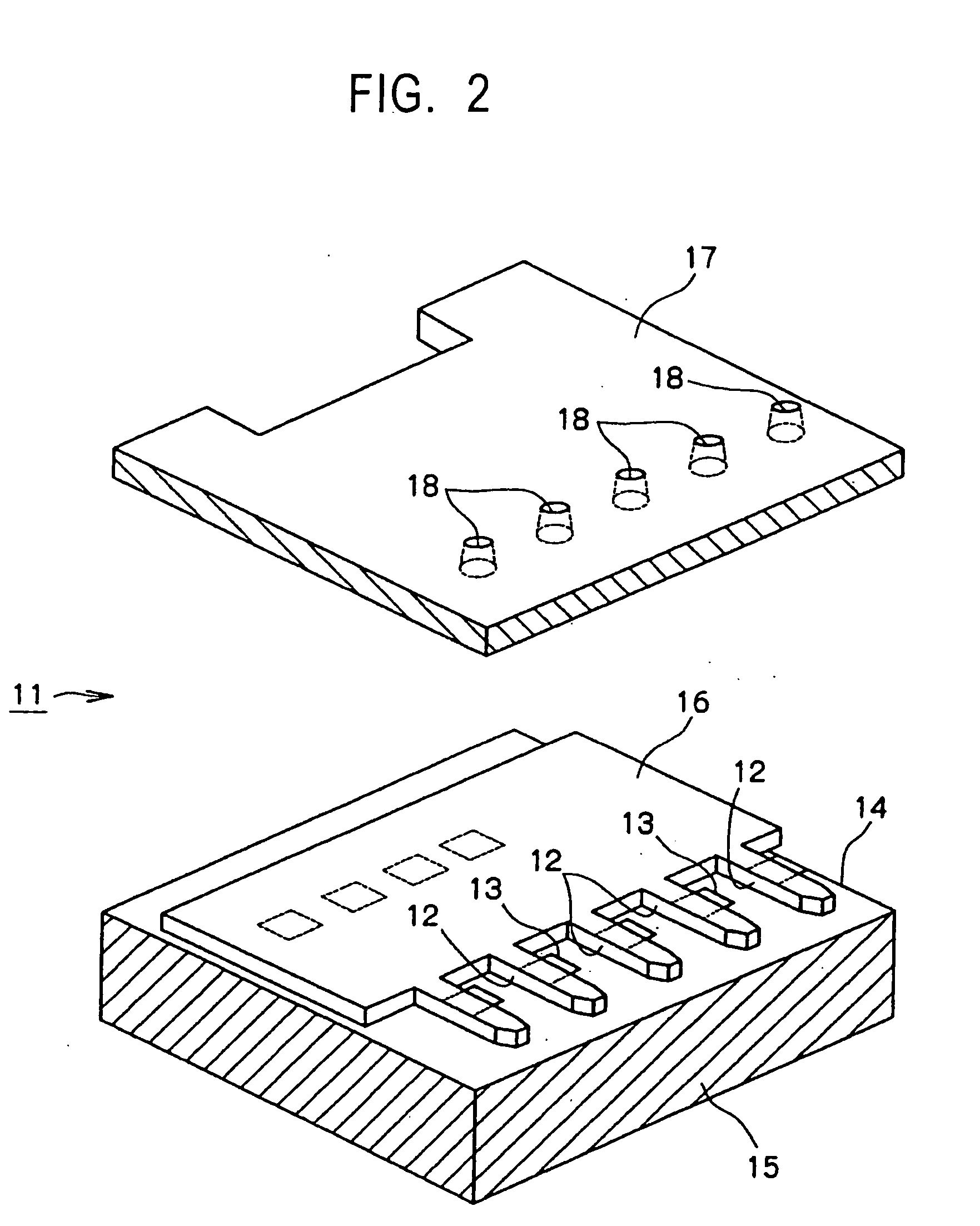
[0064]FIG. 1 is a perspective view showing a print head chip 11 included in a print head according to the present invention where a nozzle sheet 17 is adhered to the print head chip 11, and FIG. 2 is an exploded perspective view of FIG. 1 where the nozzle sheet 17 is removed.

[0065] In the print head chip 11, a base member 14 includes a semiconductor substrate 15 composed of silicon or the like and heating elements 13 formed on one side of the semiconductor substrate 15 by deposition. The heating elements 13 are electrically connected to an external circuit via conductors (not shown) formed on the semiconductor substrate 15.

[0066] A barrier layer 16 is composed of, for example, a light-curing dry film resist, and is constructed by laminating the dry film resist on the surface of the semiconductor substrate 15 on which the heating elements 13 are formed over the entire region thereof, and r...

second embodiment

[0094] (Second Embodiment)

[0095] A second embodiment achieves the above-described first object.

[0096]FIG. 8 is a plan view of a print head 30 according to the second embodiment of the present invention, which corresponds to FIG. 3 of the first embodiment.

[0097] In the print head 30 of the second embodiment, similar to the above-described known print head, the print head chips 11 are arranged in a zigzag pattern (alternately) across the ink path 20, but do not overlap each other as in the first embodiment.

[0098] When the print head chips 11 are arranged in this manner, the length of the dummy chips 31 is the same as that of the print head chips 11. Accordingly, the print head chips 11 which are free from the heating elements 13, for example, may be used as the dummy chips 31.

[0099] Other constructions are similar to those of the first embodiment, and explanations thereof are thus omitted.

third embodiment

[0100] (Third Embodiment)

[0101] A third embodiment achieves the above-described first object.

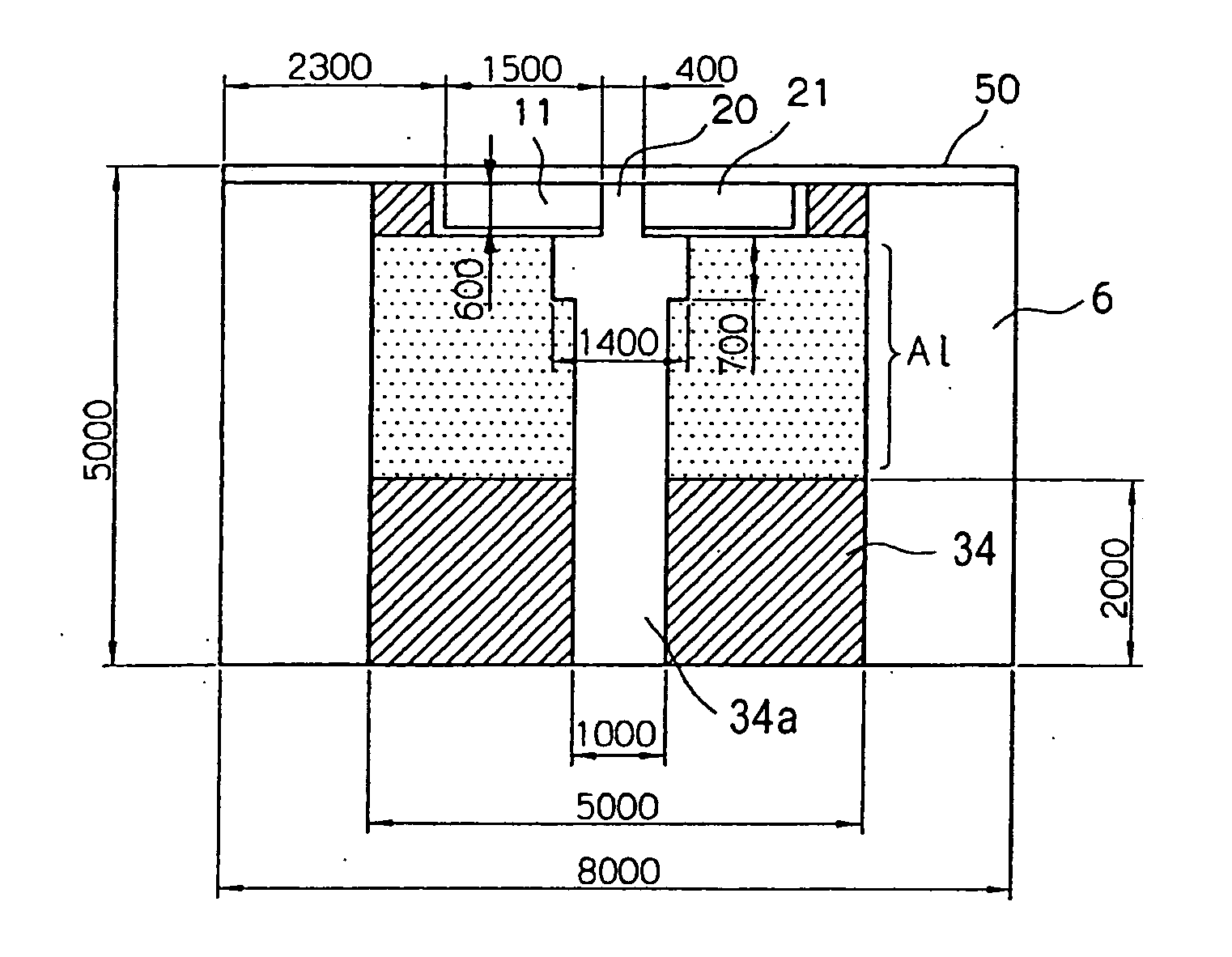
[0102]FIG. 9 is a plan view showing a print head 32 according to a third embodiment of the present invention, which corresponds to FIG. 3 of the first embodiment. FIG. 10 is a sectional view of FIG. 9 cut along line G-G, and an ink-path member 33 is also shown in FIG. 10.

[0103] The print head 32 of the third embodiment differs from that of the first embodiment in that the dummy chips 22 are not provided at both ends thereof.

[0104] In the third embodiment, both ends of the ink path 20 are closed by the ink-path member 33. Accordingly, different from the ink-path member 23 of the first embodiment, the ink-path member 33 has a projection 33b at each end thereof. The projections 33b are directly adhered to the nozzle sheet 17.

[0105] When the ink-path member 33 is constructed as described above, the shape thereof is more complex than that of the first embodiment since the projections 33b must...


PUM


Abstract

A print head for a line printer in which errors between print head chips and another component are reduced and ink leakage is prevented, and in which heat generated in print head chips is efficiently dissipated without making the structure of the print head complex or increasing the size of the print head. A plurality of print head chips (11) are arranged along an ink path (20) and are disposed on both sides of the ink path in a zigzag pattern. Dummy chips (21) which do not eject ink are disposed at regions between the print head chips (11) arranged along the ink path (20). In addition, an ink-path member (23) is provided, at least a part of the ink-path member (23) which includes portions adhered to the print head chips (11) being composed of a material having a high thermal conductivity, so that the ink-path member (23) also serves as heat-dissipating means which dissipates heat generated in the print head chips (11).

Description

TECHNICAL FIELD [0001] The present invention relates to a print head in which a plurality of print head chips are arranged, each print head chip having a plurality of ink-pressurizing cells arranged on a substrate, the ink-pressurizing cells having heating elements which are driven so as to eject ink contained in the ink-pressurizing cells through nozzles, and in particular, the present invention relates to a print head which does not cause ink leakage and a print head which exhibits an enhanced heat dissipation effect. BACKGROUND ART [0002]FIG. 21 is a schematic plan view of a print head 1 included in a known inkjet line printer. [0003] In line printers, one line is simultaneously printed on a print medium. Accordingly, the print head 1 includes a plurality of print head chips 2 (2A, 2B, . . . ) which are arranged in a direction in which lines are printed. Although only five print head chips 2A to 2E are shown in FIG. 21, more print head chips 2 are actually arranged. [0004] Althou...

Claims


Application Information

Patent Timeline
Patent Type & Authority Applications(United States)
IPC IPC(8): B41J2/145
CPCB41J2/14024B41J2/1408B41J2/14145B41J2/155B41J2202/21B41J2202/08B41J2202/11B41J2202/19B41J2202/20B41J2002/14387B41J2/05B41J2/16
Inventor EGUCHI, TAKEOTAKAKURA, MASAYUKINAKAMURA, MASATOHORII, SHINICHIUCHIDA, HIROYASUMIYAZAKI, AKIHITO
Owner SONY CORP
Why Eureka
Try Eureka