Image color adjustment

Inactive Publication Date: 2005-09-29
SEIKO EPSON CORP
View PDF20 Cites 102 Cited by
  • Summary
  • Abstract
  • Description
  • Claims
  • Application Information

AI Technical Summary

Benefits of technology

[0045] The photographer can thus select suitable correction parameters for more appropriate color correction of image data prepared under any illumination light source. Parameters which are different from the correction parameters suited for the illumination light source used to take the photographs can also

Problems solved by technology

However, conventional color balancing has not taken into consideration the distribution of colors which are nearly achromatic in the processed image.
This problem is not limited to color balancing processes, but also pertains to processes for adju

Method used


Image

  • Image color adjustment
  • Image color adjustment
  • Image color adjustment

Examples


first embodiment

B. First Embodiment

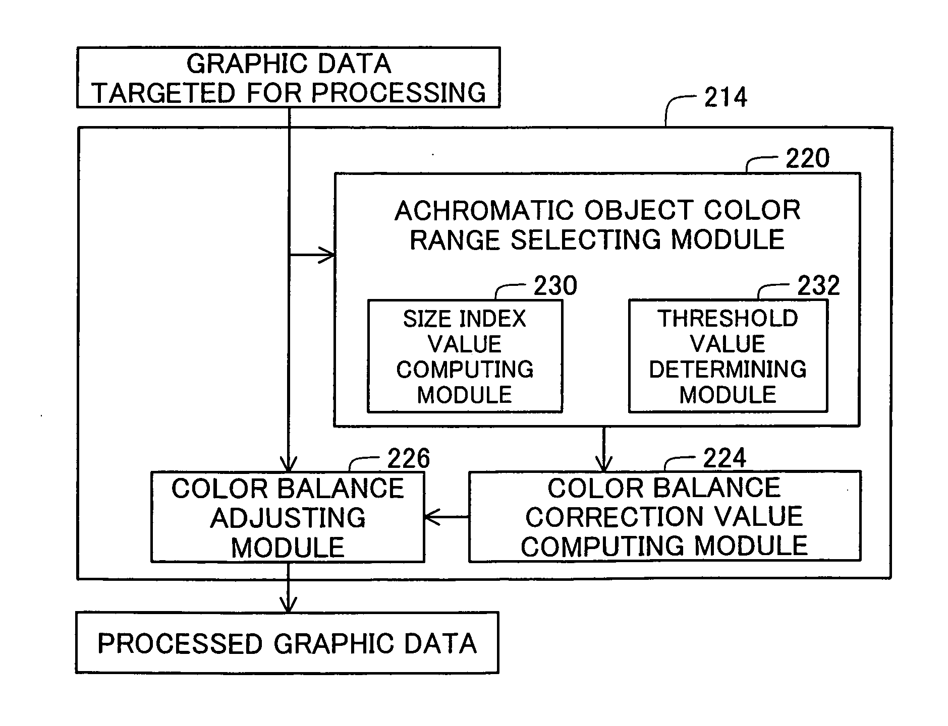
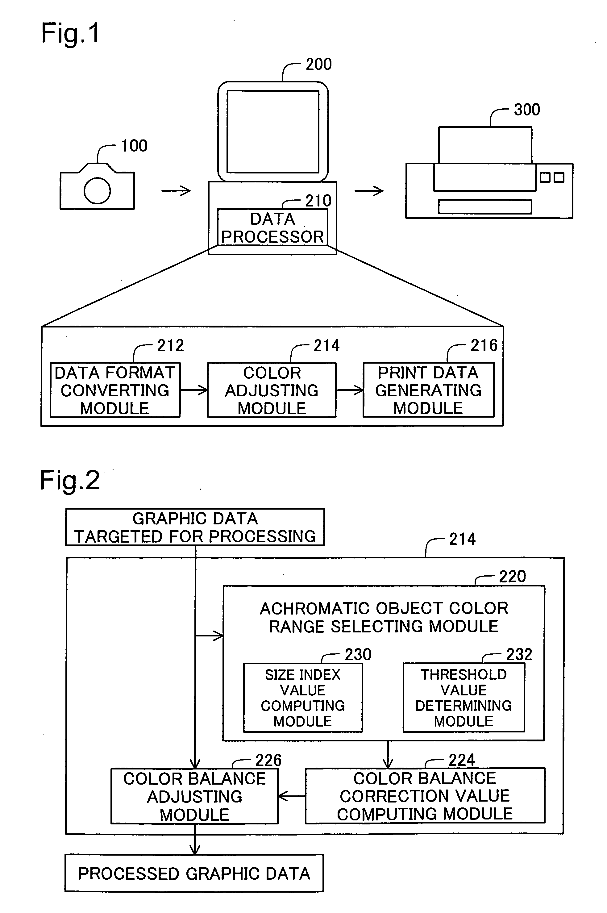
[0100]FIG. 2 is a block diagram of the internal structure of the color adjusting module 214 in the first embodiment. The color adjusting module 214 in the first embodiment comprises an achromatic object color range selecting module 220, color balance correction value computing module 224, and color balance adjusting module 226. The achromatic object color range selecting module 220 comprises a size index value computing module 230 and threshold value determining module 232. The color balance correction value computing module 224 and color balance adjusting module 226 correspond to the “color adjustment processing module” of the invention. In the first embodiment, the color adjusting module 214 adjusts the color balance of the image data targeted for processing.

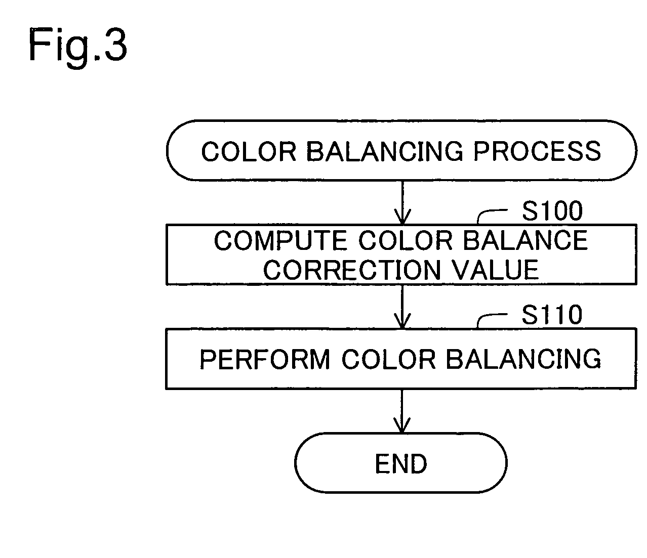
[0101]FIG. 3 is a flow chart of the procedure in the color balancing process of the color adjusting module 214 (FIG. 2). In Step S100, the achromatic object color range selecting module 220 (FIG. 2) selects...

second embodiment

C. Second Embodiment

[0142]FIG. 8 illustrates details of color balancing in a second embodiment. The difference from the first embodiment shown in FIG. 7 is that tone curve correction is done for the RGB color components of the image data targeted for processing. The structure and operation are otherwise the same as in the first embodiment.

[0143] In the second embodiment, the color balance correction value computing module 224 uses the correction values (AWB_R, AWB_B, and AWB_G) calculated in the procedure described above to calculate the tone curve correction values ΔC(R), ΔC(G), and ΔC(B) according to the following Equations (4a) through (4c).

ΔC(R)=Ka×(AWB—R−1.0)  (4a)

ΔC(G)=Ka×(AWB—G−1.0)=0.0  (4b)

ΔC(B)=Ka×(AWB—B−1.0)  (4c)

[0144] Here, Ka is a certain coefficient. The tone curve correction values ΔC(R), ΔC(G), and ΔC(B) denote the extent of correction by which an output value for a reference input value Dref is corrected from the non-correction properties. The average luminanc...

third embodiment

D. Third Embodiment

[0147]FIG. 9 is a block diagram of the internal structure of the color adjusting module 214a in the third embodiment. This differs in two ways from the first embodiment shown in FIG. 2. One difference is that a color conversion matrix selecting module 222a and color converting module 223a are provided instead of the color balance correction value computing module 224 and color balance adjusting module 226. Another difference is that the processing details of the achromatic object color range selecting module 220a are different from those of the achromatic object color range selecting module 220 in the first embodiment. Unlike the first embodiment in FIG. 2, the color adjusting module 214a executes a color conversion process on the image data targeted for processing. The structure and operation are otherwise the same as in the first embodiment. The color conversion matrix selecting module 222a and color converting module 223a also correspond to the “color adjustmen...


PUM


Abstract

At least one of a plurality of achromatic object color ranges is selected based on the image targeted for processing, and a color adjustment process is executed based on the selected achromatic object color range. Image may be reproduced using a color image data after a color correction of the color image data, the color correction being performed according to illumination light source associated with the color image data. Image data may also be output after the color correction. Image data may also be output associated with data related to the illumination light source, to reproduce the image after the color correction.

Description

CROSS-REFERENCE TO RELATED APPLICATIONS [0001] The present application claims the priority based on Japanese Patent Applications No. 2004-071038 filed on Mar. 12, 2004, No. 2004-097487 filed on Mar. 30, 2004, and No. 2004-198828 filed on Jul. 6, 2004, the disclosures of which are hereby incorporated herein by reference in theire entirety. BACKGROUND OF THE INVENTION [0002] 1. Field of the Invention [0003] The invention relates to an image color adjusting technique. [0004] 2. Description of the Related Art [0005] When images are taken using image-generating devices such as digital still cameras and video cameras, the entire image is processed by what is referred to as color balancing. The color balancing technique is disclosed, for example, in JP3469305B, JP11-205806A, JP10-210494A, and JP2-128591A. [0006] Color balancing is done to reduce colorcast in images in order to allow the photographed subject to be accurately reproduced in the original white color. Such color balancing is of...

Claims


Application Information

Patent Timeline
IPC IPC(8): H04N1/56H04N1/60H04N9/73
CPCH04N1/6077H04N9/73H04N1/6086
Inventor IMAI, SHUNFUKASAWA, KENJI
Owner SEIKO EPSON CORP
Why Eureka
Try Eureka