
Amplifying of high energy laser pulses

a laser pulse and high-energy technology, applied in the field of light amplification, can solve the problems of less than 1%, major heat dissipation problems, and low efficiency of such systems, and achieve the effects of reducing heat dissipation, reducing heat dissipation, and reducing heat dissipation

Inactive Publication Date: 2005-09-29
RAYDIANCE
View PDF5 Cites 25 Cited by
  • Summary
  • Abstract
  • Description
  • Claims
  • Application Information

AI Technical Summary

Benefits of technology

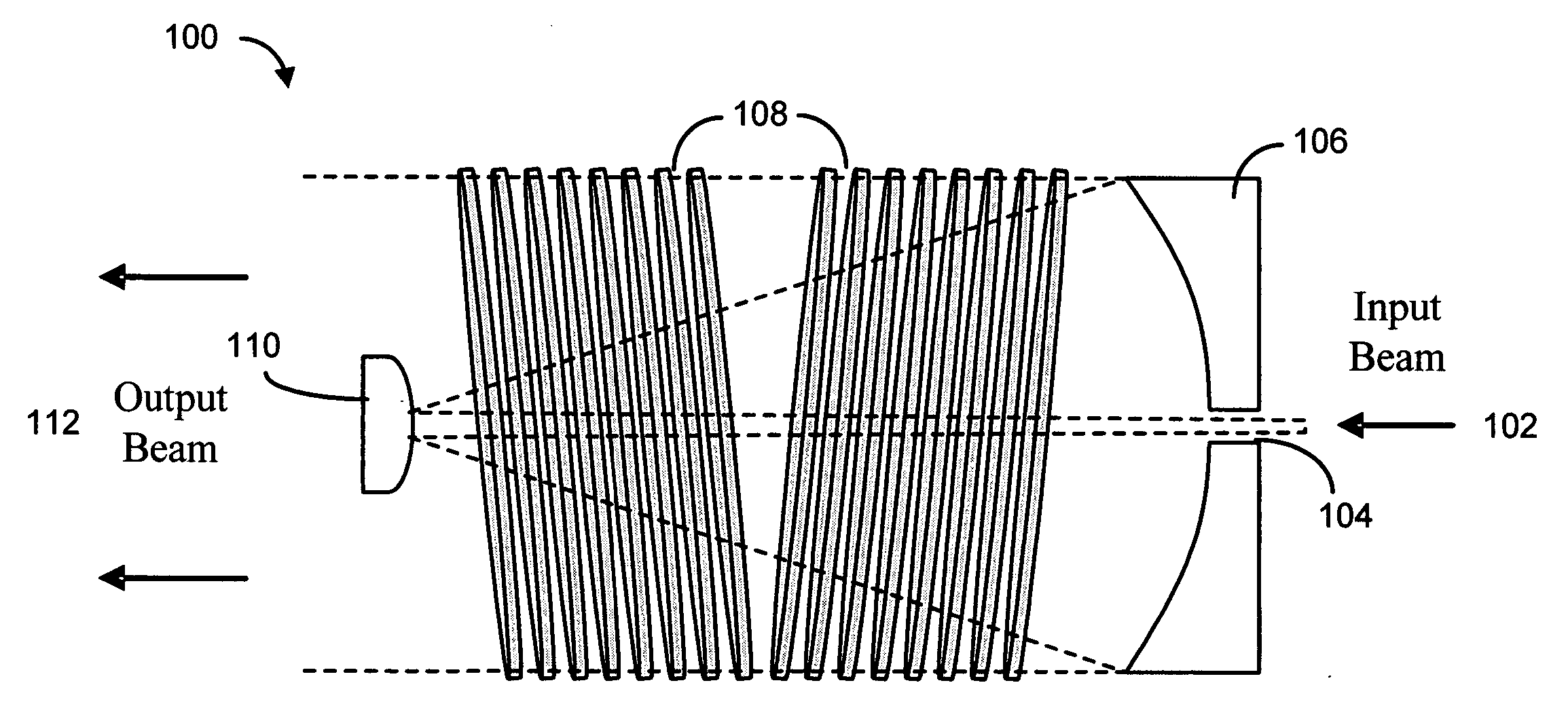
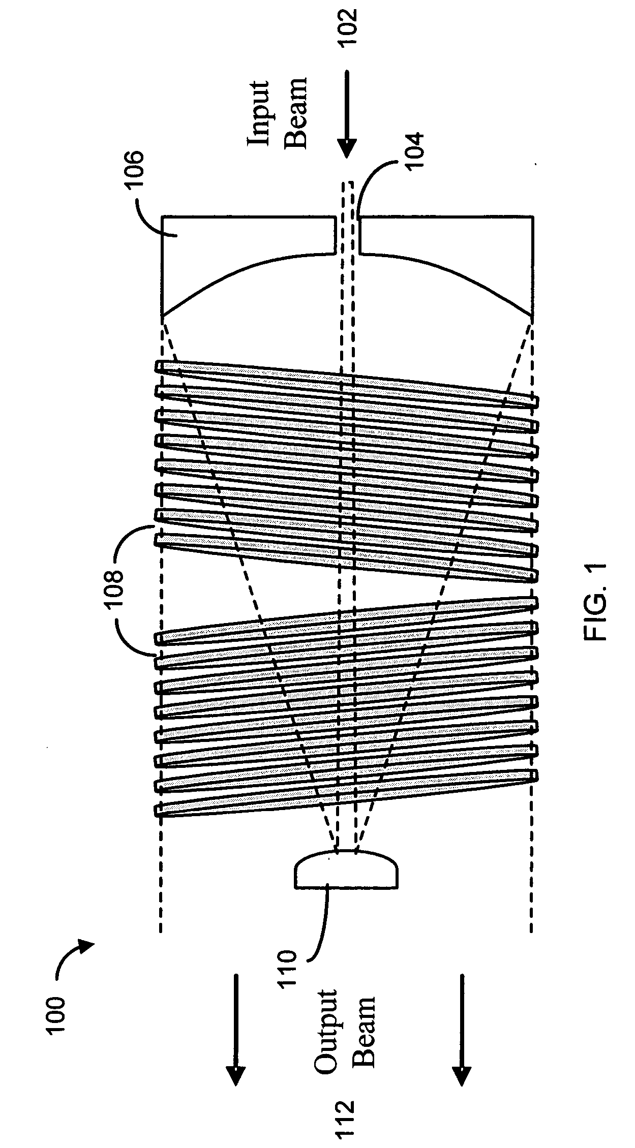
[0008] The present invention provides a method to produce a beam pattern within an amplifier that is efficient, substantially eliminates heating due to amplified spontaneous emission, is smaller and less expensive than existing systems and increases machining speed. For example, the present invention may operate at a wavelength such that the optical amplifier can be directly pumped by laser diodes emitting wavelengths of greater than 900 nm, further increasing the efficiency. Other embodiments may use different wavelengths. The present invention can obtain efficiencies of over 30%, in addition to lowering the size and cost of the system and greatly increasing machining speed.

Problems solved by technology

While solid-state laser systems can supply enough energy (in a form compressible to short-enough pulses) for the larger spot sizes, the efficiency of such systems has been very low (generally less than 1%), creating major heat dissipation problems, and thus requiring very expensive systems that provide only slow machining, due in part to low pulse repetition rates.

Method used


Image

  • Amplifying of high energy laser pulses
  • Amplifying of high energy laser pulses

Examples


Embodiment Construction

[0015] While the making and using of various embodiments of the present invention are discussed in detail below, it should be appreciated that the present invention provides many applicable inventive concepts that can be embodied in a wide variety of specific contexts. The specific embodiments discussed herein are merely illustrative of specific ways to make and use the invention and do not delimit the scope of the invention.

[0016] To facilitate the understanding of this invention, a number of terms are defined below. Terms defined herein have meanings as commonly understood by a person of ordinary skill in the areas relevant to the present invention. Terms such as “a,”“an” and “the” are not intended to refer to only a singular entity, but include the general class of which a specific example may be used for illustration. The terminology herein is used to describe specific embodiments of the invention, but their usage does not delimit the invention, except as outlined in the claims...


PUM


Abstract

The present invention provides a method of amplifying a beam of laser pulses by producing an amplified collimated beam of pulses using an amplifier, spatially spreading the amplified collimated beam of pulses into an expanded beam of pulses, introducing the expanded beam of pulses into the amplifier a second time to produce a twice amplified beam of pulses, recollimating the twice amplified beam of pulses to produce a twice amplified collimated beam of pulses such that the twice amplified collimated beam of pulses is of essentially the same cross-section as the amplifier, and introducing the twice amplified collimated beam of pulses into the amplifier a third time to produce a thrice amplified collimated beam of pulses such that the re-collimated beam sweeps essentially the entire volume of the amplifier.

Description

REFERENCE TO RELATED APPLICATIONS [0001] This application is a continuation patent application of U.S. patent application Ser. No. 10 / 849,585 filed on May 19, 2004, which claims the benefit of U.S. Provisional Patent Application Nos. 60 / 471,972 filed on May 20, 2003 (now abandoned) and 60 / 503,578 filed on Sep. 17, 2003 (now abandoned). U.S. patent application Ser. No. 10 / 849,585 incorporated the contents of U.S. Provisional Patent Application No. 60 / 539,025 filed on Jan. 13, 2004 (now abandoned) by reference. The entire content of U.S. patent application Ser. No. 10 / 849,585 filed on May 19, 2004 is hereby incorporated by reference.TECHNICAL FIELD OF THE INVENTION [0002] The present invention relates in general to the field of light amplification and, more particularly to amplification of laser pulses. BACKGROUND OF THE INVENTION [0003] Without limiting the scope of the invention, its background is described in connection with light amplification, as an example. Ablative material rem...

Claims


Application Information

Patent Timeline
Patent Type & Authority Applications(United States)
IPC IPC(8): A61B17/00A61B18/20A61B19/00
CPCA61B18/20A61B2017/00057A61B2018/00636A61B2019/461A61B2018/2035A61B2018/2095A61B2018/00904A61B2090/061A61B2018/20351A61B2018/20359A61B2018/00577
Inventor MIELKE, MICHAELBULLINGTON, JEFF
Owner RAYDIANCE
Learn More