Imaging tomography apparatus with out-of-balance compensation

Inactive Publication Date: 2005-09-29
SIEMENS AG
View PDF9 Cites 0 Cited by
  • Summary
  • Abstract
  • Description
  • Claims
  • Application Information

AI Technical Summary

Benefits of technology

[0023] It has proven to be advantageous to attach the compensation rings to the data acquisition device by means of thin

Problems solved by technology

This procedure thus is time-consuming and expensive.
The implementation of these known methods typically requires technically trained pe

Method used


Image

  • Imaging tomography apparatus with out-of-balance compensation
  • Imaging tomography apparatus with out-of-balance compensation
  • Imaging tomography apparatus with out-of-balance compensation

Examples


first embodiment

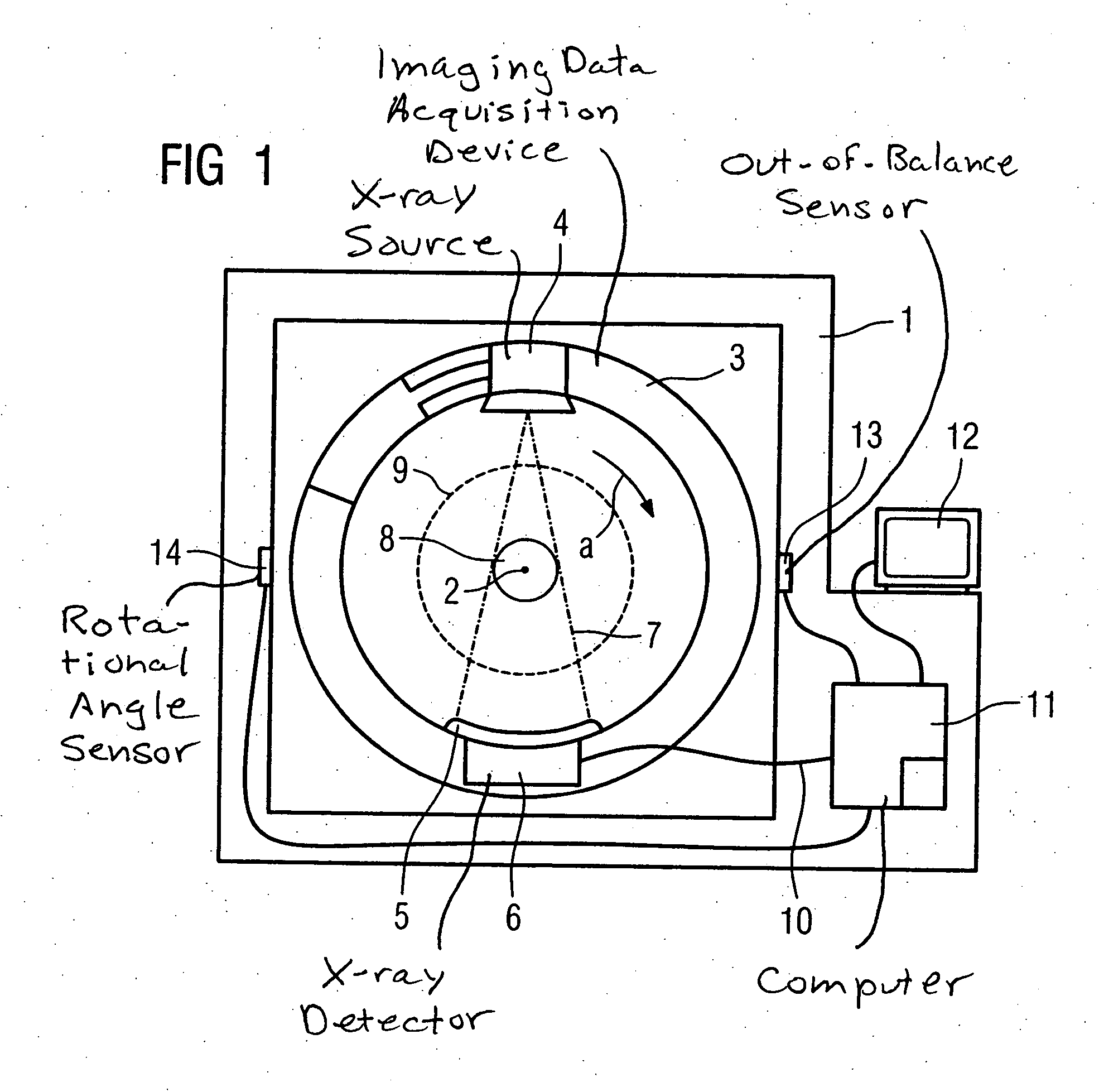
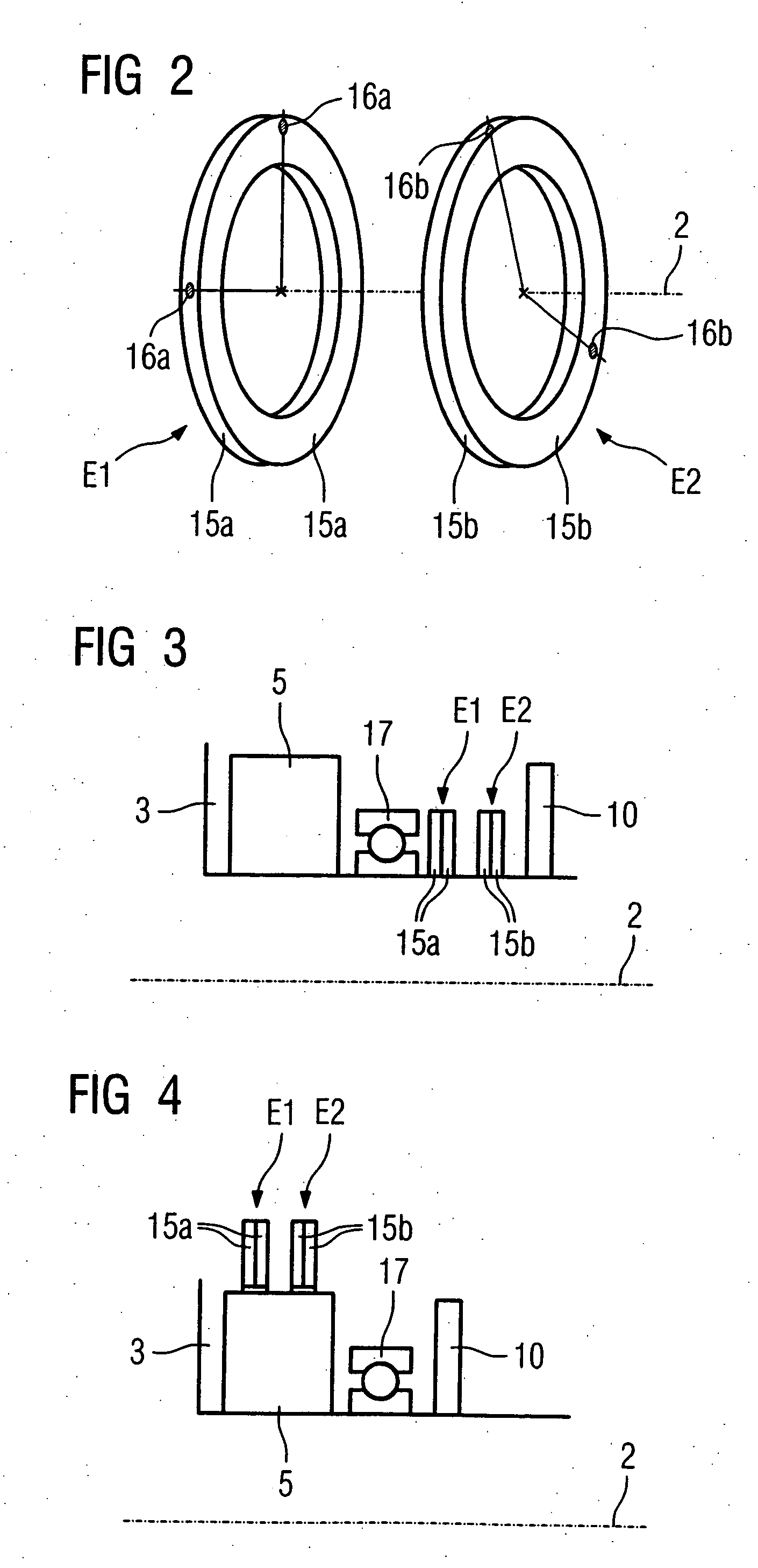
[0030]FIG. 3 schematically shows a partial cross-sectional view of the data acquisition device 3. The data acquisition device 3 is accommodated on the stationary unit (not shown) such that it can rotate around the rotational axis 2 by means of a bearing 17. The slip ring 10 is arranged on one end of the data acquisition device 3 for power supply as well as for transfer of data. Located between the x-ray detector 5 and the collector ring 10 in a first plane E1 and a second plane E2 are the first compensation rings 15a and the second compensation rings 15b arranged in pairs. The first plane E1 and the second plane E2 are separated parallel and axial to one another. An inner radius of the compensation rings 15a, 15b approximately corresponds to the inner radius of the data acquisition device 3.

second embodiment

[0031] In the data acquisition device 3 shown in FIG. 4, the compensation rings 15a, 15b surround the x-ray detector 5 and an oppositely disposed x-ray source (not shown). An outer radius of the compensation rings 15a, 15b here approximately corresponds to the outer radius of the data acquisition device 3.

[0032] Naturally, other arrangements of the compensation rings 15a, 15b are possible. The compensation rings 15a, 15b can be arranged, for example, to the left and right next to the x-ray detector 5. Alternatively, for example, the first compensation rings 15a can surround the x-ray detector 5 and the x-ray source, in contrast to which the second compensation rings 15b are arranged to the left or right next to the bearing 17.

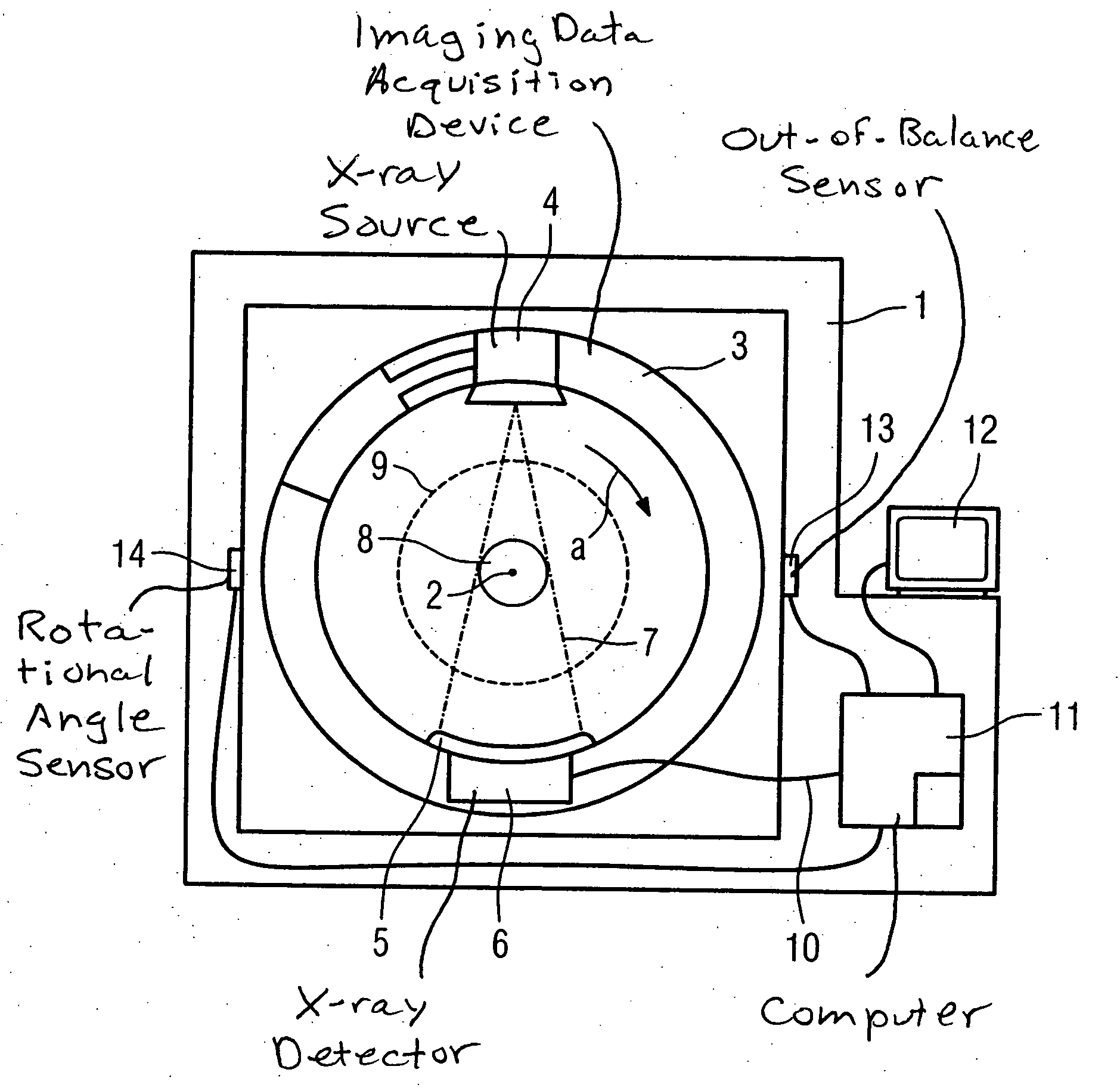
[0033] Two sensors 13 (only one of which is shown in FIG. 1) are mounted on the stationary unit 1 to measure vibrations exerted on the stationary unit 1 by an out-of-balance condition of the data acquisition device 3, with one sensor 13 for each plane E1, E2. ...


PUM


Abstract

An imaging tomography apparatus, in particular an x-ray tomography apparatus or an ultrasound tomography apparatus, has a stationary unit with a measurement unit for measurement of an out-of-balance condition, on which stationary unit is mounted an annular measurement device rotatable around a patient tunnel. Compensation weights for compensation of the out-of-balance condition are provided on the measurement device. To simplify the balancing procedure, the compensation weights are fashioned in the form of compensation rings surrounding the patient opening and with respectively defined out-of-balance conditions. The compensation rings are mounted on the measurement device such that they can be varied with regard to their relative positions in two parallel planes axially separated from one another.

Description

BACKGROUND OF THE INVENTION [0001] 1. Field of the Invention [0002] The invention concerns an imaging tomography apparatus, in particular an x-ray computed tomography apparatus. [0003] 2. Description of the Prior Art [0004] An x-ray computed tomography apparatus is known from German OS 101 08 065. A data acquisition device or gantry, mounted such that it can be rotated around a horizontal rotational axis, is accommodated in a stationary mount. A sensor to detect an out-of-balance (unbalanced) condition of the data acquisition device is provided on the stationary mount. The sensor is connected with a device to calculate the position or positions of the rotatable data acquisition device at which a compensation weight or weights should be applied to compensate the out-of-balance condition. The balancing can ensue without the use of a specific balancing device, but a trained person is required to implement the balancing procedure, in particular for correct application of the compensatio...

Claims


Application Information

Patent Timeline
IPC IPC(8): G01M1/16A61B6/03A61B8/00A61B8/06G01M1/32G01M1/36
CPCA61B6/032G01M1/32A61B8/13A61B8/06
Inventor DANZ, GUNTERMULLER, HANS-JURGEN
Owner SIEMENS AG
Why Eureka
Try Eureka