Methods and systems for intensity matching of a plurality of radiographic images

a radiographic image and intensity matching technology, applied in image enhancement, image analysis, instruments, etc., can solve the problem that the alignment of images may not be sufficient to accurately stitch images together, and achieve the effect of improving visualization of the final stitched image and minimizing some undesirable high intensity artifacts

Active Publication Date: 2005-09-29
MERATIVE US LP
View PDF27 Cites 100 Cited by
  • Summary
  • Abstract
  • Description
  • Claims
  • Application Information

AI Technical Summary

Benefits of technology

[0024] The present invention typically allows the operator to choose which type of blending method is used to blend the overlap section of the first and second image. Allowing the operator to select the method of blending provides the operator the flexibility to select the type of blending that best meets the imaging needs for that particular image dataset. The blended overlap section can be created in a variety of ways. Some methods of creating the blended overlap section include, but are not limited to maximum intensity projection (MIP), minimum intensity projection (MinIP), average, smooth transition, and the like. Depending on the desired effect on the image, in exemplary embodiments the operator will be given a choice as to which blending method is used. For example, if the operator wants to highlight high density objects, the operator can select a maximum intensity projection. If the operator wants to minimize some undesirable high intensity artifacts introduced by the imaging device, the operator can select the minimum intensity projection. For instance, notice FIG. 29, because of edge artifacts in the original images, the Maximum IP preserves these and they can be seen as thin wedges in the central portion of the stitched image. In contrast as shown in FIG. 30, the Minimum IP does not show these wedges, but no...

Problems solved by technology

Because anatomic landmarks are variable, having only one type of marker available ...

Method used


Image

  • Methods and systems for intensity matching of a plurality of radiographic images
  • Methods and systems for intensity matching of a plurality of radiographic images
  • Methods and systems for intensity matching of a plurality of radiographic images

Examples


Embodiment Construction

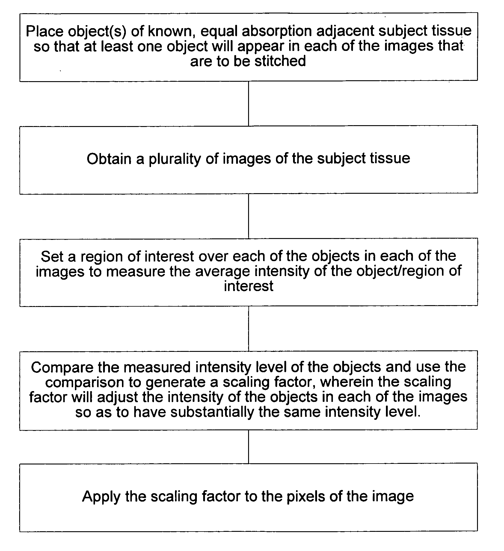
[0083] The present invention provides improved methods, systems, software and graphical user interfaces for allowing an operator to stitch and / or blend a plurality of DICOM digital radiographic images together.

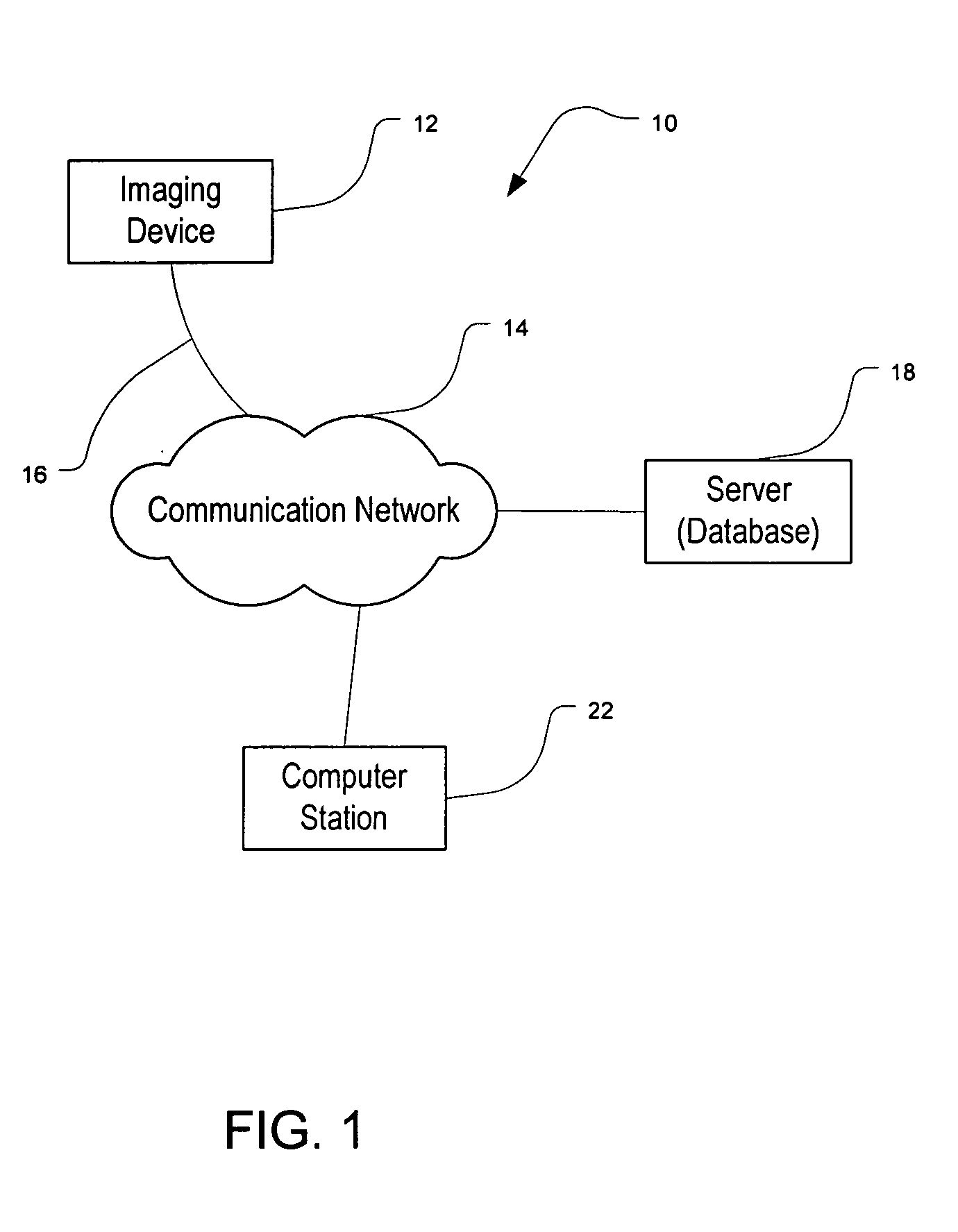
[0084]FIG. 1 is a simplified block diagram of a system 10 which may incorporate the present invention. As shown, system 10 comprises an imaging device 12, such as an x-ray, MRI, CT, ultrasound, nuclear imaging device, or the like that is coupled to a communication network 14 (such as an intranet, LAN, WAN, or the internet) via communication link(s) 16. System 10 depicted in FIG. 1 includes a computer system 22 that communicates with the imaging device that can run software for manipulating images obtained from imaging device 16. It should be appreciated however, that system 10 depicted in FIG. 1 is merely illustrative of an embodiment incorporating the present invention and does not limit the scope of the present invention. For example, instead of delivering the image data to...


PUM


Abstract

Methods and systems for intensity/brightness matching of a plurality of radiographic images. Software can be used to provide various stitching and blending methods to join first and second images into a composite, larger image before or after the intensity/brightness of the radiographic images are modified.

Description

CROSS-REFERENCES TO RELATED APPLICATIONS [0001] The present invention claims benefit to U.S. Provisional Patent Application Ser. No. 60 / 550,215, filed Mar. 4, 2004, entitled “Methods and Systems for Combining the Display Intensities of a Plurality of Radiographic Images,” the complete disclosure of which is incorporated herein by reference. The present invention is also a continuation-in-part of U.S. patent application Ser. No. 10 / 005,473, filed Nov. 6, 2001, entitled “Methods and Systems for Combining a Plurality of Radiographic images,” which claims benefit of U.S. Provisional Patent Application Ser. No. 60 / 308,997, filed Jul. 30, 2001, entitled “Methods and Systems for Combining a Plurality of Radiographic Images,” the complete disclosures of which are incorporated herein by reference. [0002] The present invention is also related to U.S. patent application Ser. No. 09 / 908,466, filed Jul. 17, 2001, the complete disclosure of which is incorporated herein by reference.BACKGROUND OF ...

Claims


Application Information

Patent Timeline
IPC IPC(8): G06K1/00G06T3/00G06T5/40G06T7/00
CPCG06T3/4038G06T5/008G06T2207/30004G06T7/0028G06T2207/20221G06T5/40G06T7/33
Inventor KREANG-AREKUL, SOMCHAIKAUFMAN, LEON
Owner MERATIVE US LP
Why Eureka
Try Eureka