Optical modulator

Inactive Publication Date: 2005-09-29
FUJITSU LTD
View PDF8 Cites 38 Cited by
  • Summary
  • Abstract
  • Description
  • Claims
  • Application Information

AI Technical Summary

Benefits of technology

[0008] The present invention has been conceived in light of the foregoing problem and provides an optical modulator (e.g., an RZ optical modulator) which is forme

Problems solved by technology

However, the working length [the length of a portion of the optical modulator where an electric signal (the clock signal or the data signal) acts on the light propagating through the optical waveguide; corresponding to the length of a signal e

Method used


Image

  • Optical modulator
  • Optical modulator
  • Optical modulator

Examples


Example

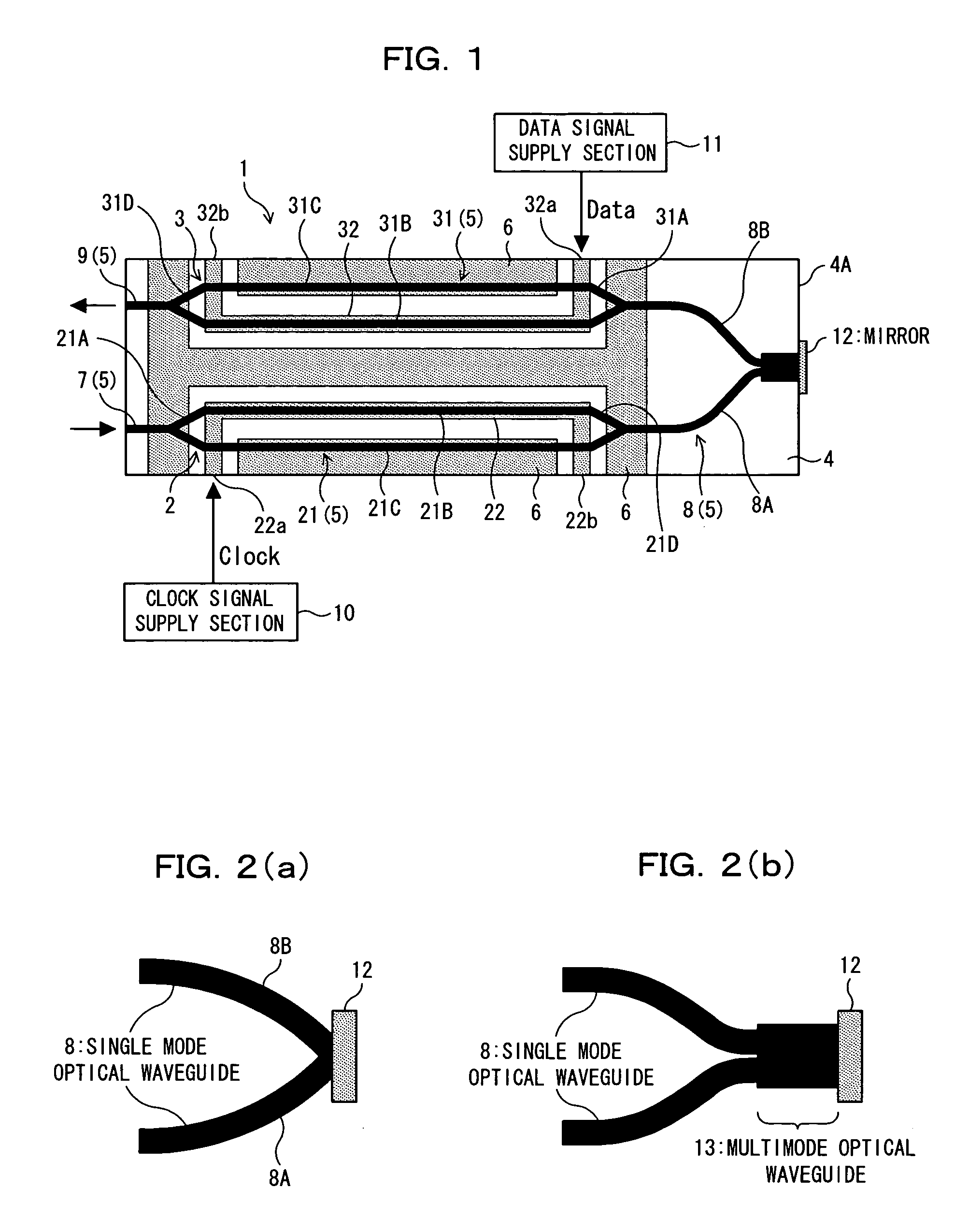
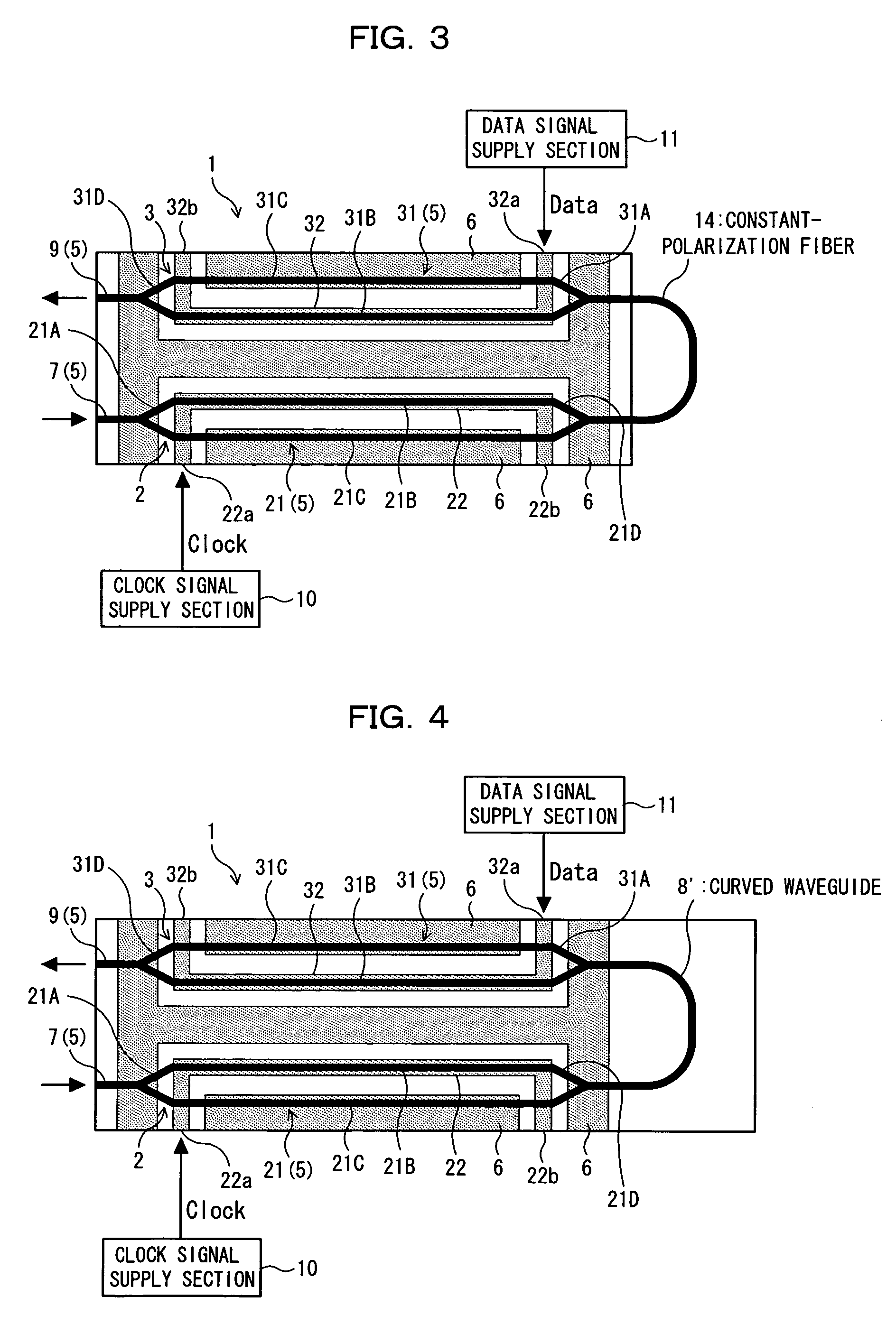
[0039] An optical modulator according to an embodiment of the present invention will be described hereunder by reference to FIGS. 1 to 6.

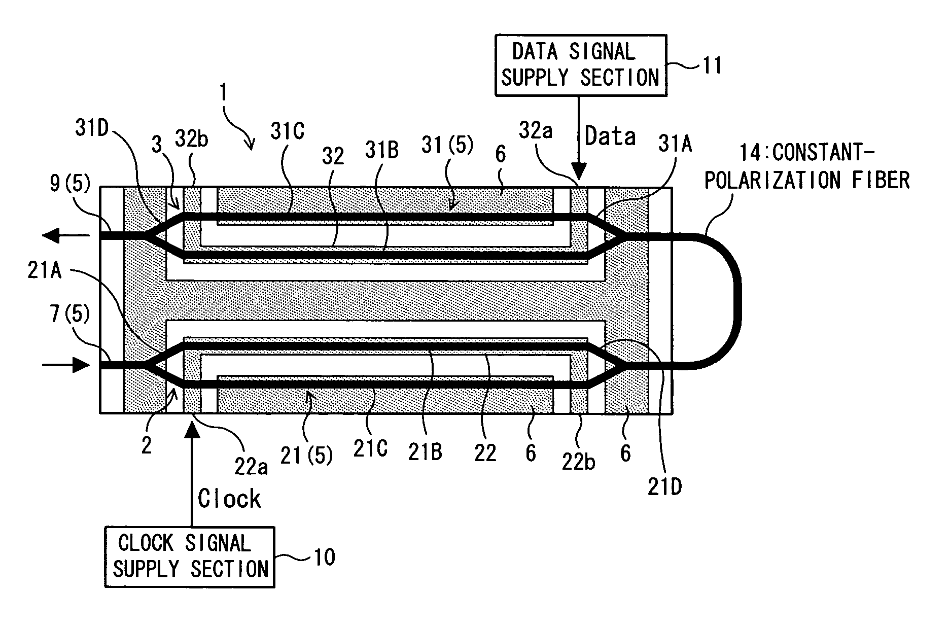
[0040] In the present embodiment, an RZ optical modulator [an optical modulator (an optical modulator of clock modulation type) which generates an RZ (Return to Zero) signal by supplying a clock signal and a data signal to input light] is described by reference to FIGS. 1 to 6. The RZ optical modulator is used as, e.g., an optical transmitter in a long-distance optical transmission system.

[0041] As shown in FIG. 1, in the present embodiment, an RZ optical modulator 1 is configured as having Mach-Zehnder optical modulators (MZ-type LN optical modulators) 2, 3 which are of two stages and use lithium niobate (LiNbO3; LN).

[0042] As shown in FIG. 1, the RZ optical modulator 1 has the following structure. An optical waveguide 5 including a first Mach-Zehnder optical waveguide (hereinafter called a first optical waveguide) 21 and a second Mach-Zehnder ...


PUM


Abstract

In relation to an optical modulator (e.g., an RZ optical modulator) formed from a plurality of Mach-Zehnder optical modulators, in an attempt to make the optical modulator compact and realize a low drive voltage, the optical modulator is formed by comprising a plurality of Mach-Zehnder optical modulators, each including a substrate exhibiting an electro-optical effect, an optical waveguide formed on the substrate, and electrodes formed in the vicinity of the optical waveguide. The plurality of Mach-Zehnder optical modulators are arranged on the substrate and connected into multistage.

Description

FIELD OF THE INVENTION [0001] The present invention relates to an optical modulator used in optical communication. BACKGROUND [0002] In efforts to realize a ultrahigh-speed, broadband optical communications network, high expectations are placed on an optical modulator (an external modulator) of external modulation system. [0003] Particularly, development of a Mach-Zehnder optical modulator using LiNbO3 (lithium niobate; LN) that exhibits a superior high-speed modulation characteristic and a dispersion-resistant characteristic is pursued to enable long-distance transmission of an optical signal. [0004] As shown in FIG. 10, an RZ optical modulator 100 comprising two Mach-Zehnder optical modulators 101, 102 connected in tandem has recently been put forth as an optical modulator capable of generating an RZ (Return to Zero) signal. This RZ optical modulator 100 can produce an RZ-modulated optical signal by causing an electric signal of a clock (a clock signal) to enter one Mach-Zehnder o...

Claims


Application Information

Patent Timeline
IPC IPC(8): G02F1/035G02F1/21G02F1/225
CPCG02F1/2255G02F2201/34G02F2001/212G02F1/212
Inventor SUGIYAMA, MASAKIDOI, MASAHARUNAKAZAWA, TADAONAKAZAWA, YUMI
Owner FUJITSU LTD
Why Eureka
Try Eureka