Wall and ceiling fastening system and methods therefor

a technology for fastening systems and ceilings, applied in the direction of fastening means, securing devices, dowels, etc., can solve the problems of multiple fasteners, difficulty in keeping toggles, and higher cost associated with manufacturing metal anchors, so as to reduce the risk of wall blowout

Inactive Publication Date: 2005-09-29
ILLINOIS TOOL WORKS INC
View PDF22 Cites 19 Cited by
  • Summary
  • Abstract
  • Description
  • Claims
  • Application Information

AI Technical Summary

Benefits of technology

[0015] Advantages of the fastening system of the present invention include eliminating the need for pre-drilling, reducing the risk of wall blowout resulting from b

Problems solved by technology

Disadvantages include the need to pre-drill an oversized hole, difficulty in keeping the toggles from spinning while trying to tighten the screw against the toggles, multiple fastener sizes for multiple screw sizes, and the higher cost associated with manufacturing metal anchors.
Disadvantages include the need to pre-drill an oversized hole, difficulty in keeping the toggle stationary while trying to tighten the screw against the toggle, multiple toggle sizes for multiple screw sizes, and the higher cost associated with manufacturing metal anchors.
Disadvantages of this system include the need for pre-drilling an oversized hole.
In addition, if the flaps are improperly drawn toward the inside surface of the wall, the inside surface is crushed thereby weakening the load bearing ability of the wall.
This method is disadvantageous because pre-drilling is needed.
In addition, the opening of the split sleeves often crushes the back of the wall thereby reducing the load-bearing capacity of the wall.
Often, as increasing torque is placed on the anchor as the screw is driven in, the anchor will often cause the wall to fail, enabling the anchor to begin spinning in place and severely compromising the wall's capacity to grip the anchor securely.
Disadvantages i

Method used


Image

  • Wall and ceiling fastening system and methods therefor
  • Wall and ceiling fastening system and methods therefor
  • Wall and ceiling fastening system and methods therefor

Examples


Embodiment Construction

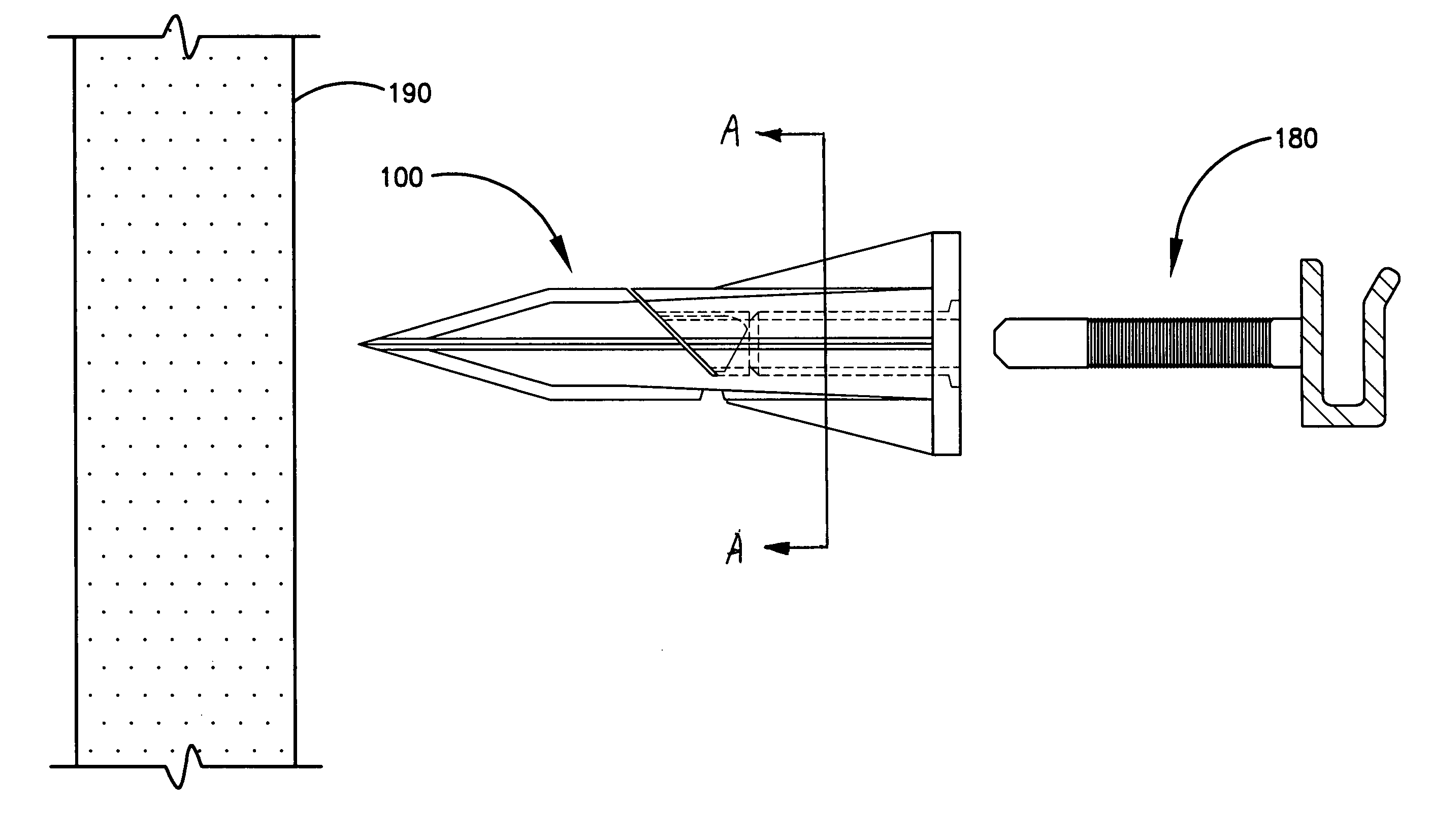
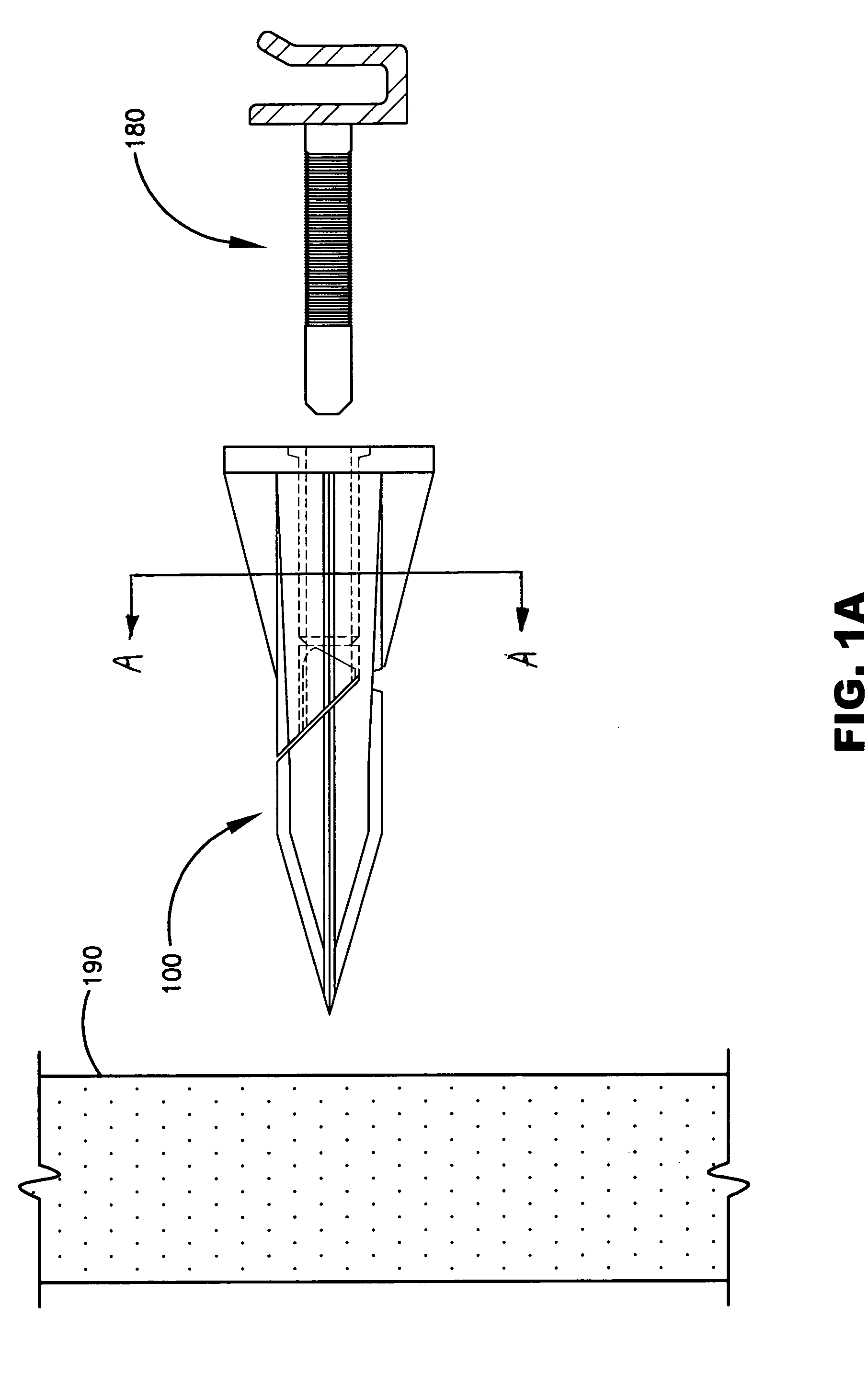
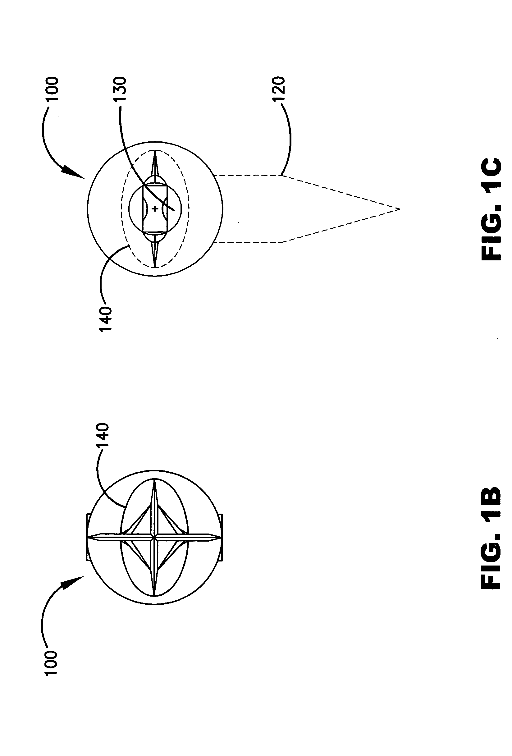
[0026] The present invention will now be described in detail with reference to a few preferred embodiments thereof as illustrated in the accompanying drawings. In the following description, numerous specific details are set forth in order to provide a thorough understanding of the present invention. It will be apparent, however, to one skilled in the art, that the present invention may be practiced without some or all of these specific details. In other instances, well known process steps and / or structures have not been described in detail in order to not unnecessarily obscure the present invention. The features and advantages of the present invention may be better understood with reference to the drawings and discussions that follow.

[0027] To facilitate discussion, FIGS. 1A-1E, 2A-2E, 3A-3D, 4A-4D, 5A-5C, and 6A-6C illustrate various views and installation stages of the wall and ceiling fastening system and methods of the present invention. In addition, “wallboard” is used interch...


PUM


Abstract

A wall and ceiling fastening system and method useful for applications such as hanging or securing objects to hollow walls and ceilings is provided. In one embodiment, the fastening system includes a drivable anchor having at least one pivotable section and a pin configured to be inserted into a channel of the anchor. The anchor is driven into a wallboard of the wall or ceiling with a hammer or a suitable tool. As the pin is inserted into the anchor, a lever or rack and pinion action between the pin and the pivotable section causes the pivotable section to pivot towards and come into contact with an interior surface of the wallboard. Depending on the fastening application, the pin can have a suitable head such as a pan screw head, a flat screw head, a round screw head, an oval screw head, a countersunk screw head, a machine screw head, a hook head, an eye hook head, a ring head, a swivel head, a shoulder head, a nut, a bolt head or other suitable head. In addition, the pin can have a ratcheted body, a threaded body, or a ribbed body. In some embodiments, the cross-sectional profile of the anchor is elongated so as to provide a larger supporting surface between the anchor and the wallboard. In addition, the cross-sectional profile of the anchor channel can be elongated so that a wider range of pin body sizes and types can be accommodated. The anchor body may also have one of more stabilizing ribs.

Description

BACKGROUND OF THE INVENTION [0001] The present invention relates to mounting systems. More particularly, the present invention relates to methods and apparatus for mounting fasteners to hollow walls and ceilings. [0002] Most walls and ceilings of residential and commercial structures are hollow cavity construction. Typically, “drywall”, also known in the trade as gypsum board, is nailed, glued and / or screwed to a suitable frame which includes as wood or metal studs and / or joists, spaced sixteen or twenty-four inches on center, to form these walls. Another less common wall and ceiling material with similar characteristics is plaster. A variety of fastening systems are commercially available for attaching fasteners to these walls to hang or secure objects such as pictures, mirrors and shelving, cabinetry, towel racks, hand rails or any object that requires anchorage at a location in the wall or ceiling other than where a framing member is located. Most fasteners can be divided into se...

Claims


Application Information

Patent Timeline
IPC IPC(8): F16B1/00F16B13/00F16B13/08F16B13/12
CPCF16B13/001F16B13/12F16B13/0833F16B13/002
Inventor BROWN, BRIAN A.BROWN, GREGORY A. M.
Owner ILLINOIS TOOL WORKS INC
Why Eureka
Try Eureka