Air-passage opening/closing device

a technology of air passage and opening/closing device, which is applied in the direction of vehicle maintenance, vehicle cleaning, operating means/releasing devices for valves, etc., can solve the problems of increasing the production cost of film members and the production cost of air passage opening/closing devices, so as to prevent noise, effectively restrict air leakage, and reduce the size of the case

Inactive Publication Date: 2005-09-29
DENSO CORP
View PDF9 Cites 9 Cited by
  • Summary
  • Abstract
  • Description
  • Claims
  • Application Information

AI Technical Summary

Benefits of technology

[0007] It is another object of the present invention to provide an air passage opening / closing device including a film member, which can prevent sliding friction from being generated between the film member and a unit case when an air passage in the unit case is opened and closed by the film member.
[0017] When the film member is unwound from the film winding shaft at the side of the other end while the film winding shaft moves in the first direction, a part of the film member is separated from a seal surface of the case around the opening of the air passage in a protrusion shape due to a wound habit of the film member. However, in the present invention, the seal surface is bent in accordance with the protrusion shape of the film member to protrude in the same direction as the protrusion shape of the film member. Therefore, it can effectively restrict air leakage from being generated, thereby preventing noise due to vibration of the film member.

Problems solved by technology

As a result, a special material, which has low friction, and large tensile strength and large tear strength against the friction force, is required to be used as the film member, thereby increasing production cost of the film member.
Further, because drive force for moving the film member is increased due to the sliding friction force of the film member, a high torque actuator is required for driving the film member, thereby further increasing production cost of the air passage opening / closing device.

Method used


Image

  • Air-passage opening/closing device
  • Air-passage opening/closing device
  • Air-passage opening/closing device

Examples


first embodiment

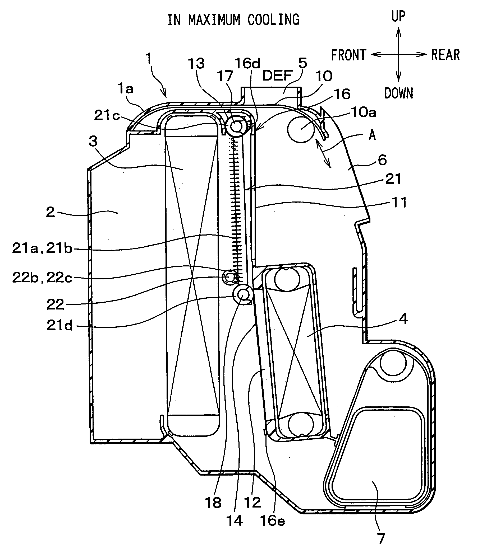
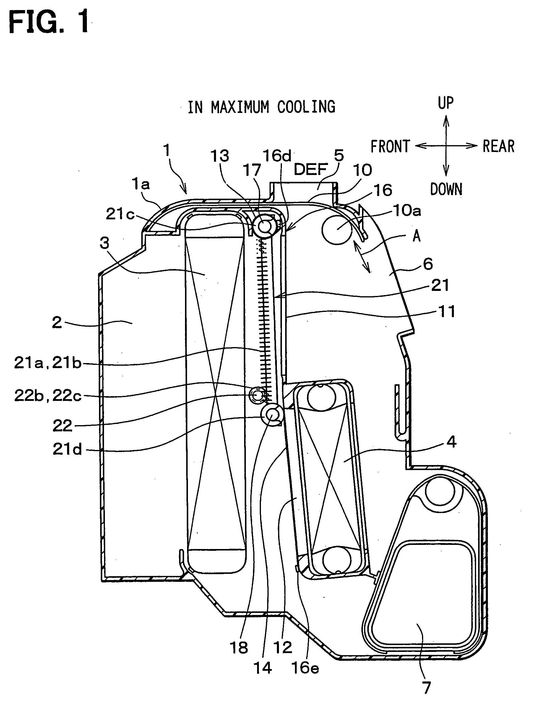
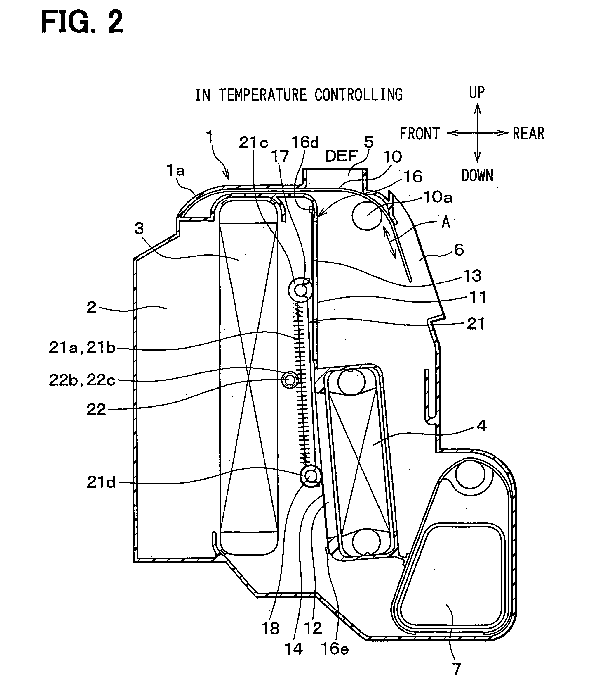
[0045] The first embodiment of the present invention will be now described with reference to FIGS. 1-5. In the first embodiment, an air passage opening / closing device according to the present invention is typically used for a vehicle air conditioner. As shown in FIGS. 1-4, an air conditioning unit 1 of a vehicle air conditioner includes a resinous air conditioning case 1a. The air conditioning case 1a is disposed inside a dashboard in a passenger compartment at an approximately center in a vehicle width direction (right-left direction). Further, the air conditioning unit 1 is mounted in the vehicle to correspond to the arrangement direction in FIGS. 1-4 in a vehicle front-rear direction, in a vehicle up-down direction and in a vehicle right-left direction. An air inlet space 2, into which air blown by a blower unit (not shown) flows through a connection duct 1b shown in FIG. 4, is formed at a front most side in the air conditioning case 1a. In a vehicle having a right steering wheel...

second embodiment

[0079] In the first embodiment, the pitches of the linear gears 19, 20 are changed in accordance with the changes of the wound diameters of the film members 13, 14, respectively, so that the changes of the winding length and the unwinding length of the film winding shafts 17, 18 are absorbed to prevent the film members 13, 14 from being loosed. However, in the second embodiment, the circular gears 17a, 18a are separated from the film winding shafts 17, 18, and a spring member is disposed between the separated circular gear 17a and the film winding shaft 17. Further, another spring member is disposed between the separated circular gear 18a and the film wind shaft 18. The rotational phase difference is set between the separated circular gear 17a and the film wind shaft 17, and between the separated circular gear 18a and the film wind shaft 18, thereby compensating the changes of the winding length and the winding off length of the film winding shafts 17, 18 due to the wound diameter c...

third embodiment

[0082] In the above-described second embodiment, because the coil spring 23 has a relatively short length, the winding off operation of the coil spring 23 is ended at a position between the maximum wound diameter of the film member 13 and the minimum wound diameter thereof, and at a position between the maximum wound diameter of the film member 14 and the minimum wound diameter thereof. After the winding off operation of the coil spring 23 is ended, the tensile force of the coil spring 23 disappears.

[0083] However, in the third embodiment, as shown in FIG. 7, the film winding shaft 17 is formed in a cylindrical shape, and a spring support shaft 24 separated from the film winding shaft 17 is rotatably fitted in a cylindrical inner spaces 17c of the film winding shaft 17. An end portion 24a of the spring support shaft 24 protrudes outside the film winding shaft 17, and is fitted into the circular shaft holder 21c of the moving member 21 at the right side. An end portion 17d of the fi...


PUM


Abstract

An air passage opening / closing device includes a film member for opening and closing an opening of an air passage of a case. One end of the film member is fixed to a fixing portion on an outer periphery of the opening of the air passage, and the other end thereof is connected to a film winding shaft. A moving member movable by rotation of a drive shaft is provided on the opening, and the film winding shaft is moved while being rotated by the movement of the moving member, so that the film member at the other end side is wound around and unwound from the film winding shaft. Accordingly, when the air passage is opened and closed by the film member, sliding friction can be prevented from being generated between the film member and the case.

Description

CROSS-REFERENCE TO RELATED APPLICATION [0001] This application is a divisional application of U.S. application Ser. No. 10 / 397,124 filed Mar. 26, 2003 related to and claims priority from Japanese Patent Applications No. 2002-88831 filed on Mar. 27, 2002, No. 2002-351215 filed on Dec. 3, 2002 and No. 2003-29597 filed on Feb. 6, 2003, the contents of which are hereby incorporated by reference.BACKGROUND OF THE INVENTION [0002] 1. Field of the Invention [0003] The present invention relates to an air passage opening / closing device which opens and closes an air passage by using a film member (a film door). The air passage opening / closing device is suitably used for a vehicle air conditioner. [0004] 2. Related Art [0005] An air passage opening / closing device, which opens and closes an air passage by using a film member, is proposed in JP-A-5-23824 and the like. In this related art, both ends of a film member having an opening are attached to film winding shafts rotatably mounted in an air...

Claims


Application Information

Patent Timeline
Patent Type & Authority Applications(United States)
IPC IPC(8): B60H1/00
CPCB60H1/00692Y10S251/901B60H2001/00728B60H1/00857
Inventor OKUMURA, YOSHIHIKONISHIKAWA, KATSUMITOKUNAGA, TAKAHIROITO, KOJI
Owner DENSO CORP
Why Eureka
Try Eureka