Combination of golf club head body and striking plate

Inactive Publication Date: 2005-09-29
FUSHENG IND CO LTD
View PDF12 Cites 21 Cited by
  • Summary
  • Abstract
  • Description
  • Claims
  • Application Information

AI Technical Summary

Benefits of technology

[0007] An object of the present invention is to provide a combination of a club head body and a striking plate, wherein positioning of the striking plate in the clu

Problems solved by technology

However, a space delimited by the ball-striking plate, the shoulder, and the protruded portion receives a limited amount of welding material.
Further, a portion of the welding material is used to fill slits between an inner perimeter delimiting the recess and an outer perimeter of the ball-striking plate such that the remaining amount of welding material becomes insufficient.
As a result, the joining areas of brazing are apt to crack when the ball-striking plate hits a

Method used


Image

  • Combination of golf club head body and striking plate
  • Combination of golf club head body and striking plate
  • Combination of golf club head body and striking plate

Examples


first embodiment

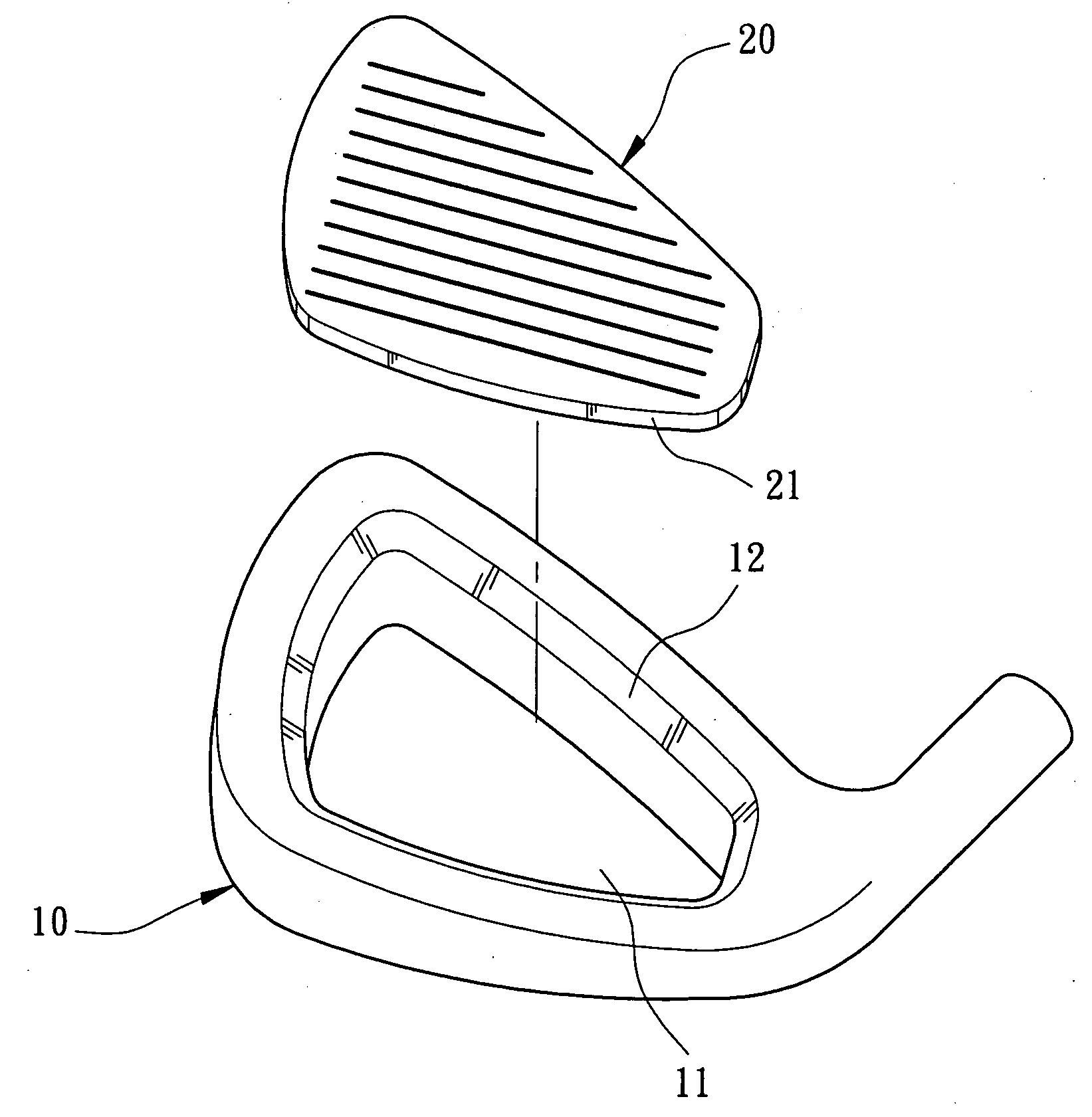
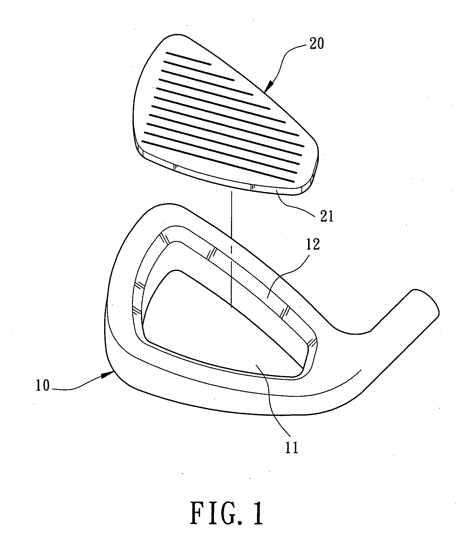
[0025] Referring to FIGS. 1 through 3, a first embodiment in accordance with the present invention includes a club head body 10 and a striking plate 20. The club head body 10 includes is made of stainless steel, titanium alloy, carbon steel, low-alloy steel, cast iron, nickel-base alloy, structural steel, Fe—Mn—Al alloy, or super alloy. The club head body 10 includes an opening 11 in a front side thereof. A perimeter that delimits the opening 11 forms an inner engaging face 12. Preferably, the inner engaging face 12 tapers rearward and may be a planar face or an arcuate face.

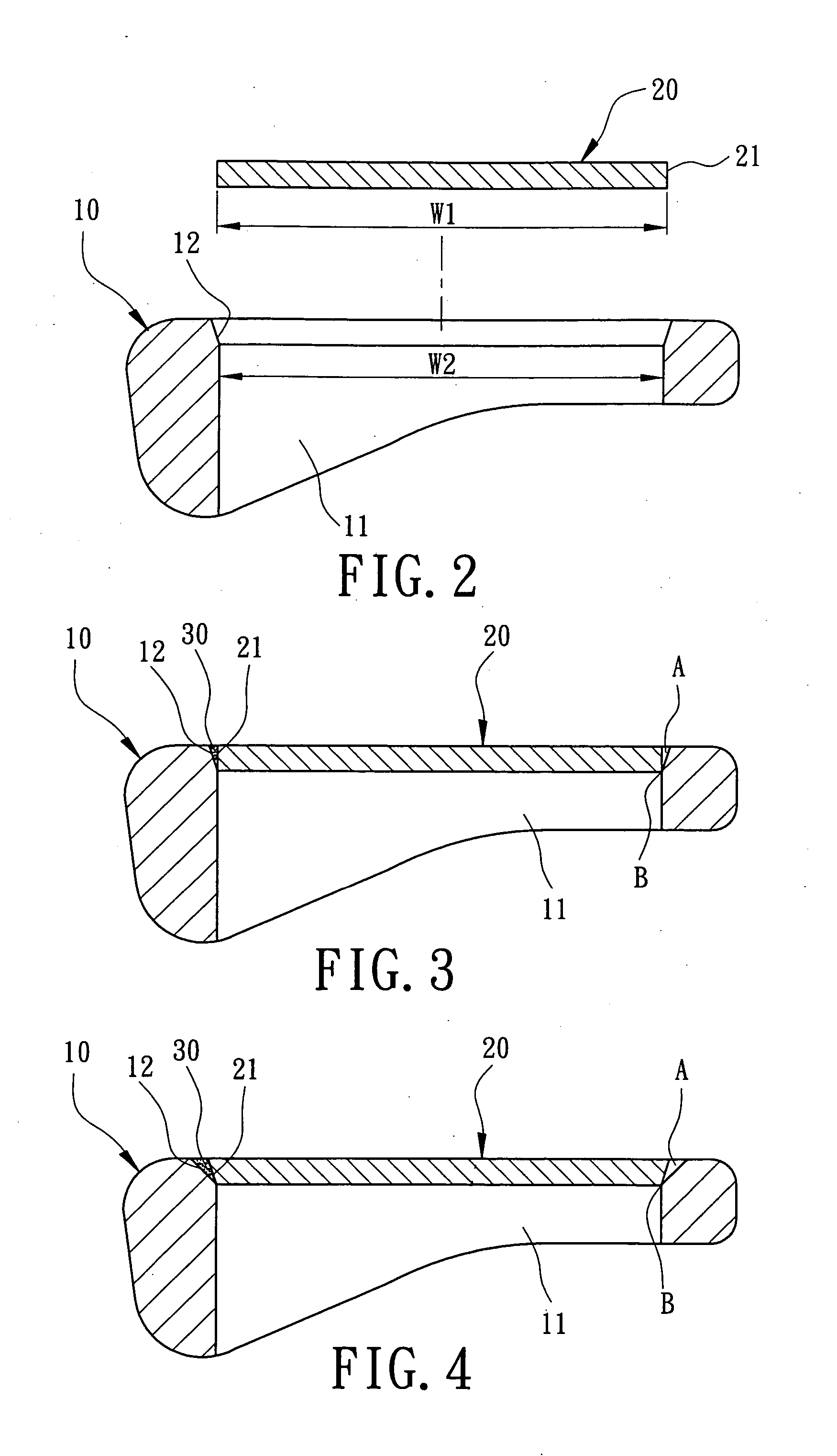
[0026] The striking plate 20 includes a front face (not labeled) for striking a golf ball (not shown). The striking plate 20 further includes an outer perimeter that forms an outer engaging face 21. As illustrated in FIG. 2, a maximum width w1 of a rear end portion of the outer engaging face 21 is larger than a maximum width w2 of a rear end portion of the inner engaging face 12.

[0027] In assembly, as shown in ...

second embodiment

[0030]FIG. 4 illustrates the present invention, wherein the outer engaging face 21 of the striking plate 20 tapers reward. Nevertheless, the outer engaging face 21 extends in an inclining angle different from that of the inner engaging face 12. Again, the rear end portion of the outer engaging face 21 tightly abuts against the inner engaging face 12 to form an abutting section B, and a filler-receiving space A is formed between the inner engaging face 12 and the outer engaging face 21. Positioning in the subsequent welding process is simplified. Improved welding effect, improved welding convenience, and improved bonding reliability are provided. Further, the outer engaging face 21 can be planar or arcuate.

[0031]FIGS. 5 through 7 illustrate a third embodiment of the present invention modified from the first embodiment. In this embodiment, the outer perimeter of the striking plate 20 includes a first outer engaging face 21 on a rear end portion thereof and a second outer engaging face...

fourth embodiment

[0032]FIGS. 8 through 10 illustrate the present invention, wherein the inner perimeter delimiting the opening 11 of the club head body 10 includes a first inner engaging face 12 on a front end portion thereof and a second inner engaging face 12′ on a rear end portion thereof. The first inner engaging face 12 and the second inner engaging face 12′ taper rearward, with the first inner engaging face 12 extending in an inclining angle different from that of the second inner engaging face 12′, and with the second inner engaging face 12′ extending in an inclining angle the same as that of the outer engaging face 21. Thus, the second inner engaging face 12′ of the club head body 10 is in intimate contact with the a rear end portion of the outer engaging face 21 of the striking plate 20 to form an abutting section B. A filler-receiving space A is formed between a front end portion of the outer engaging face 21 of the striking plate 20 and the second inner engaging face 12′ of the club head ...


PUM


Abstract

In a combination of a club head body and a striking plate, the club head body includes an opening in a front end thereof, a perimeter delimiting the opening forming an inner engaging face. The striking plate includes a front face for striking a golf ball, the striking plate including an outer perimeter that forms an outer engaging face. The striking plate is received in the opening of the club head body. The inner engaging face and the outer engaging face together form a filler-receiving space for receiving a welding material. Further, the inner engaging face and the outer engaging face together form an abutting section that reliably retains the striking plate in place for a subsequent welding process.

Description

BACKGROUND OF THE INVENTION [0001] 1. Field of the Invention [0002] The present invention relates to a combination of a golf club head and a striking plate. In particular, the present invention relates to a combination of a golf club head and a striking plate in which the golf club head and the striking plate together provide a reliable engaging relationship therebetween to improve welding reliability and to simplify positioning for the assembling procedure. [0003] 2. Description of Related Art [0004] U.S. Pat. No. 5,871,408 discloses a method for fusing a ball-striking plate with a golf club head case. A golf club head case of a metal material is prepared and includes a recess having a shoulder located in a bottom of the recess. The shoulder of the recess of the golf club head case has a deformable protruded portion in an outer edge thereof for enhancing the fusion of the ball-striking plate with the recess of the golf club head case. A ball-striking plate of a metal material is pr...

Claims


Application Information

Patent Timeline
IPC IPC(8): A63B53/04
CPCA63B2053/0416A63B53/047A63B53/0416
Inventor HUANG, CHUN-YUNGCHEN, CHAN-TUNG
Owner FUSHENG IND CO LTD
Why Eureka
Try Eureka