Bone fixation implants

a bone fixation and implant technology, applied in the field of implants for bone fixation, can solve the problems of cumbersome and quick identification of some surgeons, difficult for some surgeons to readily distinguish the top and bottom surfaces of implants, and limited success of measures, so as to reduce the likelihood of failure and the highest stress

Inactive Publication Date: 2005-09-29
DEPUY SYNTHES PROD INC
View PDF30 Cites 111 Cited by
  • Summary
  • Abstract
  • Description
  • Claims
  • Application Information

AI Technical Summary

Benefits of technology

[0015] It should be recognized that the transverse openings also advantageously promote elongate plates to bend between, and not at the fastener holes. The fastener holes are typically the weakest part of the pla

Problems solved by technology

In addition, resorbable implants (e.g., plates and meshes) are relatively translucent and semi-transparent in appearance which may make it difficult for some surgeons to readily distinguish the top and bottom surfaces of the implant.
Thus, the size of these craniofacial implants and/or the type of mat

Method used


Image

  • Bone fixation implants
  • Bone fixation implants
  • Bone fixation implants

Examples


Embodiment Construction

[0046] In the description that follows, any reference to direction or orientation is merely intended for convenience of description and is not intended in any way to limit the scope of the present invention. Moreover, the features and benefits of the invention are illustrated by reference to the preferred embodiments. Accordingly, the invention expressly should not be limited to such preferred embodiments illustrating some possible non-limiting combination of features that may exist in alone or in other combinations of features, and which should only be limited by the claims appended hereto.

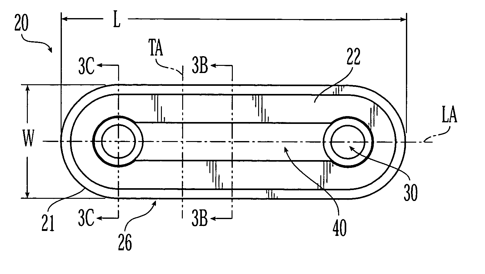
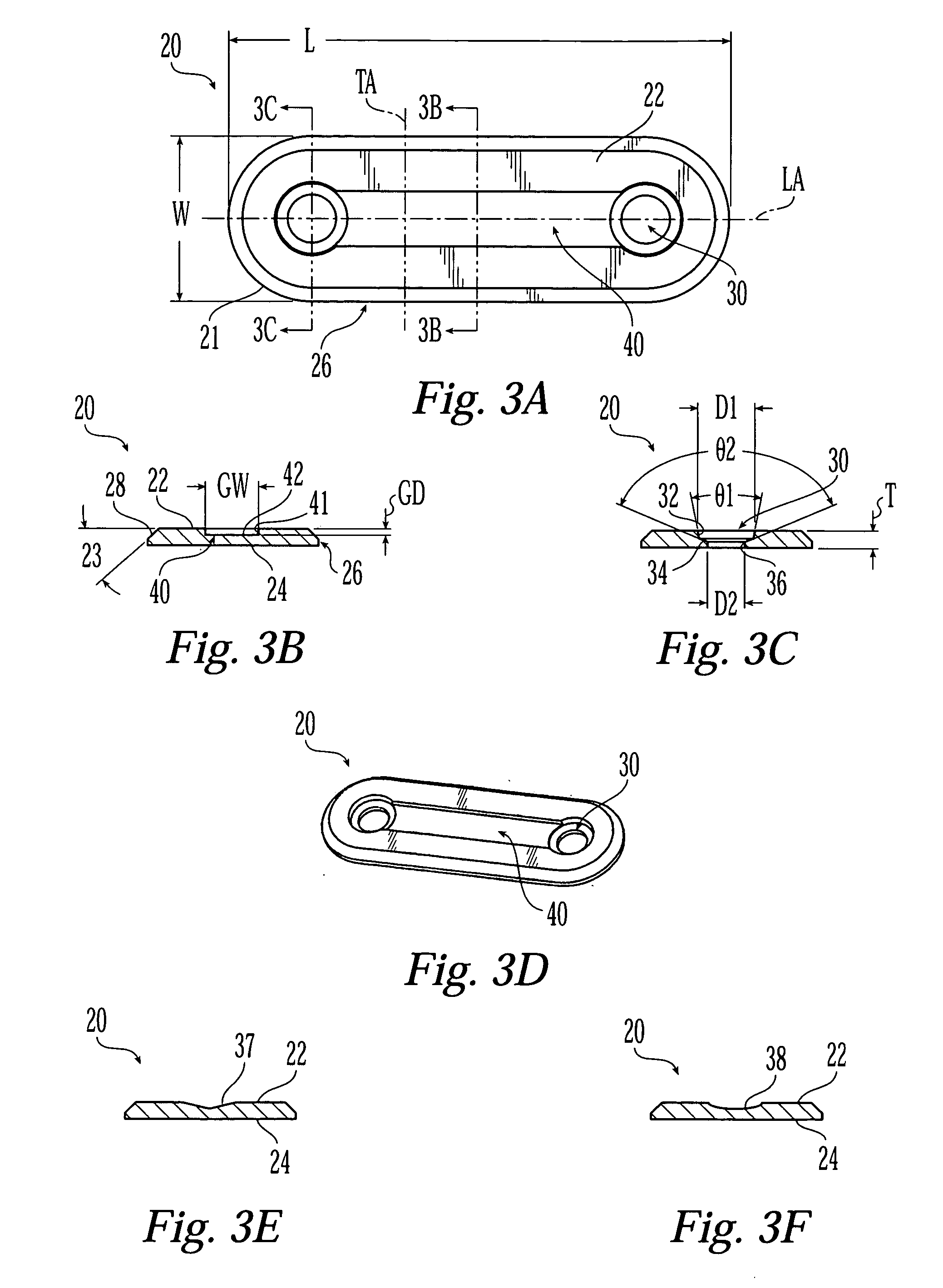
[0047] FIGS. 3A-D depict one embodiment of an implant for bone fixation in the form of a bone plate. The bone plate 20 has a generally elongate body defining a longitudinal axis LA extending along the centerline of the plate, and a transverse axis TA extending perpendicular to the longitudinal axis. Plate 20 includes two ends 21, a top surface 22, a bottom bone-contacting surface 24, two longitu...


PUM


Abstract

The present invention is generally directed to an improved bone fixation implant that provides tactile indication of the top surface of the implant. In one embodiment, an implant comprises a top surface, a bottom bone-contacting surface, and recessed portion disposed in the top surface of the implant to provide a tactile indicator for readily identifying the top surface of the implant. In another embodiment, the top surface indicator may be in the form of an elongated top surface groove that is recessed below the top surface of the implant. The implant may further include at least two fastener holes for receiving fasteners therethrough to secure the implant to the bone. In preferred embodiments, the implant may be made of a resorbable or metallic materials. In another embodiment of the present invention, an implant may comprise transverse slots preferably disposed between at least some of the fastener holes.

Description

FIELD OF THE INVENTION [0001] The present invention generally relates to implants for bone fixation such as plates and meshes, and more particularly to improved implants having for example an indicator that permits the top surface of the implant to be more easily detected during surgery. BACKGROUND OF THE INVENTION [0002] Biologically compatible metallic and resorbable implants, such as differently shaped plates and meshes, have been used in craniofacial surgical bone repair applications. Such implants are used to mend bone discontinuities resulting from trauma-induced fractures or osteotomies necessitated by various surgical procedures. These implants are commonly secured to the bone with various types and shapes of fasteners, such as screws and tacks. Craniofacial plating has been offered in a variety of configurations including plates with straight-sides (as shown in FIG. 1) or undulating sides being wider at the fastener holes than between the holes (as shown in FIG. 2). The und...

Claims


Application Information

Patent Timeline
IPC IPC(8): A61B17/00A61B17/68A61B17/80A61B17/86
CPCA61B17/68A61B17/80A61B17/8052A61B2017/00004A61B17/8071A61B17/8085A61B17/8605A61B17/8061A61B17/58A61F2/28
Inventor ZWIRNMANN, RALPH FRITZVAUGHEN, DOUGLAS HOWARDCHEN, MICHAEL
Owner DEPUY SYNTHES PROD INC
Why Eureka
Try Eureka