Storage system

a storage system and storage subsystem technology, applied in the field of storage systems, can solve the problems of inability to optimally locate the volumes according to the state of use of each storage subsystem, inability to move data across different types of storage subsystems, and high cost of storage subsystem products, so as to achieve the effect of easy ascertaining the volume of each volume and shortening the tim

Active Publication Date: 2005-09-29
GOOGLE LLC
View PDF3 Cites 44 Cited by
  • Summary
  • Abstract
  • Description
  • Claims
  • Application Information

AI Technical Summary

Benefits of technology

[0013] An object of this invention is the provision of a storage system capable of relocation of volumes according to the state of use of storage subsystems with different processing performance. An object of this invention is the provision of a storage system enabling the easy ascertainment of each volume, even when volumes are relocated in an environment in which different types of storage subsystems coexist. An object of this invention is the provision of a storage system capable of relocation of volumes in a shorter amount of time, in an environment in which different types of storage subsystems coexist.
[0016] The collection / analysis portion collects and analyzes information relating to the states of use of each storage subsystem. Information relating to a state of use may be, for example, information enabling the direct or indirect measurement of the frequency of use of a volume, such as the number of input / output operations per unit time. The volume transition management portion moves a volume between storage subsystems based on states of use. Volume movement is executed by performing volume copying spanning storage subsystems. A volume with a high frequency of use is moved to a storage subsystem with high processing performance, and a volume with low frequency of use is moved to a storage subsystem with low processing performance. By this means, the responsiveness of volumes with high frequencies of use is improved, and storage resources for the storage system overall can be used more efficiently.
[0019] Prior to the beginning of volume movement by the volume transition management portion, a communication path for volume movement between storage subsystems can be set provisionally. By provisionally setting a communication path, the trouble involved in establishing a communication session upon execution of volume copying can be eliminated, and volumes can be moved more quickly.
[0020] A pool area to secure in advance unused volumes for use in volume movement by the volume transition management portion can also be comprised. Volume movement is realized by volume copying. By securing in advance an unused volume for use in volume copying, the occurrence of shortages of unused volumes, with a consequent effect on volume movement, can be prevented in advance.

Problems solved by technology

However, in conventional technology data cannot be relocated spanning different types of storage subsystems.
Moreover, in conventional technology it is possible to copy the contents of volumes spanning storage subsystems, but this is merely performed for purposes of so-called disaster recovery, and optimal location of volumes according to the state of use of each storage subsystem is not possible.
Further, the quantity of data to be managed by enterprises, municipalities, schools and other organizations increases each year, and while there is always a desire for storage systems with enhanced performance, storage subsystems are expensive system products.
However, conventional technology does not take into consideration the relocation of volumes in an environment in which different storage subsystems coexist, so that automatic relocation of volumes according to the state of use is not possible even when there is uneven use among storage subsystems; consequently such systems cannot be used efficiently.
For example, after the initial construction of a system, there are cases in which the frequency of use of a storage subsystem with relatively poor performance is greater than the frequency of use of a high-performance storage subsystem.
And, there are cases in which the frequency of use of a volume placed in a high-performance storage subsystem declines, so that the storage resources of the high-performance storage subsystem are wasted.
Hence the tasks involved are complex, and the storage system is difficult to use.

Method used


Image

  • Storage system
  • Storage system
  • Storage system

Examples


Embodiment Construction

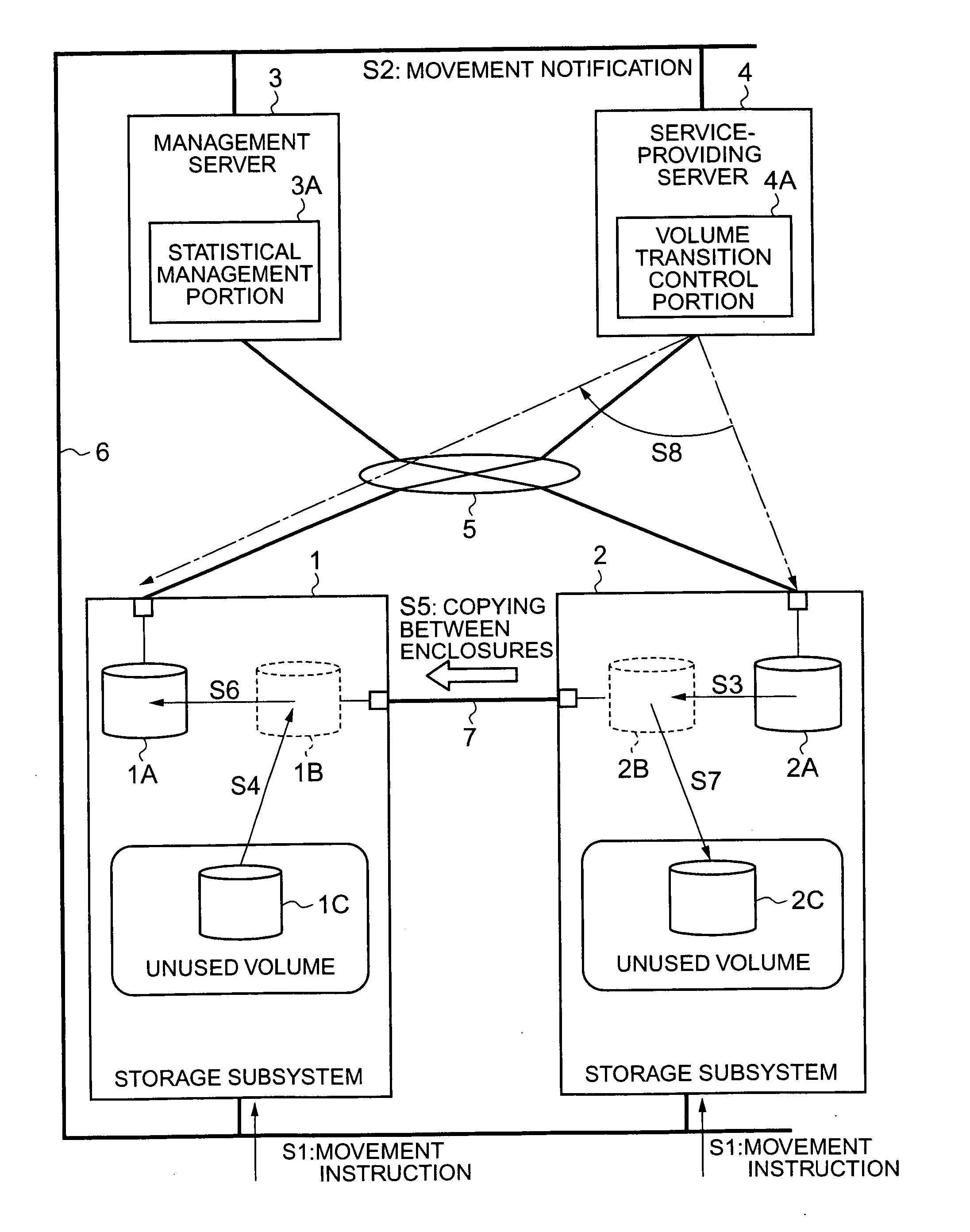
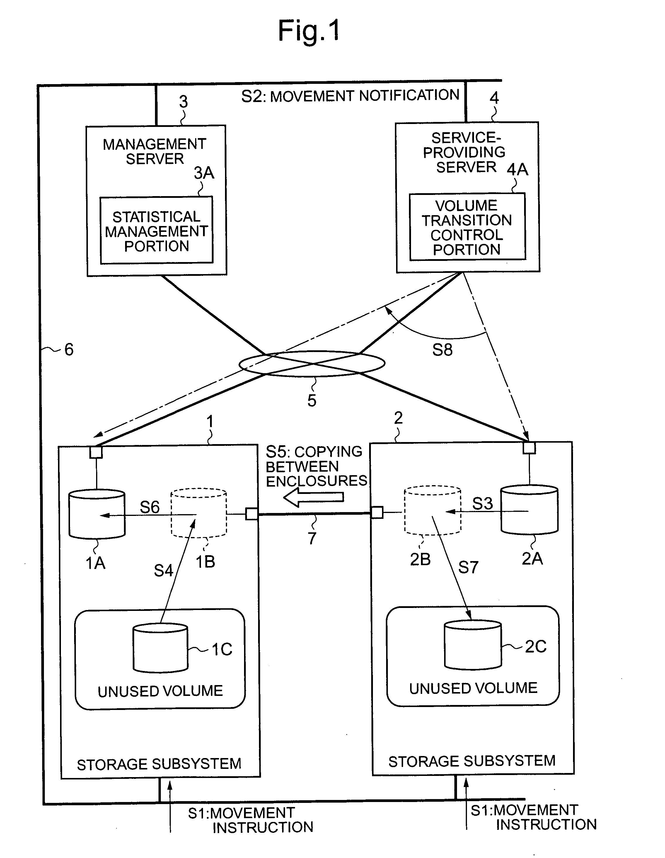
[0034] Below, an aspect of this invention is explained based on the drawings. In the aspect, a storage system is disclosed comprising a plurality of storage subsystems with different processing performance, a service-providing server which accesses and exchanges data with the storage subsystems, and a management server connected with each of the storage subsystems and with the service-providing server and which manages the storage subsystem.

[0035] The management server comprises a collection / analysis portion, which collects information relating to states of use of storage subsystems; a volume transition management portion, which based on analyzed states of use moves volumes with relatively high frequencies of use to storage subsystems with relatively high processing performance among the storage subsystems and moves volumes with relatively low frequencies of use to storage subsystems with relatively low processing performance among the storage subsystems; and a unique identifying i...


PUM


Abstract

According to this invention, in an environment in which are intermixed a plurality of storage subsystems with different processing performance, volumes are automatically relocated according to the state of use of each storage subsystem. A storage system comprises a plurality of storage subsystems 1, 2 with different processing performance. When unevenness occurs in the states of use of the storage subsystems 1, 2, and movement of a volume 2A becomes necessary, a management server 3 issues an instruction for volume movement to the copy source system 2 and to the copy target system 1 (S1). The management server 3 notifies a service-providing server 4 of the volume movement (S2). At the copy source, the volume 2A is allocated to a dummy volume 2B (S3), and at the copy target, an unused volume 1C is allocated to a dummy volume 1B (S4). Then volume copying is executed, and the volume is moved between the storage subsystems 1, 2.

Description

CROSS-REFERENCE TO RELATED APPLICATIONS [0001] This application relates to and claims priority from Japanese Patent Application No. 2004-091064 filed on Mar. 26, 2004, the entire disclosure of which is incorporated herein by reference. BACKGROUND OF THE INVENTION [0002] 1. Field of the Invention [0003] This invention relates to a storage system comprising a plurality of different types of storage subsystems with different processing performance. [0004] 2. Description of the Related Art [0005] A storage system is configured with for example disk drives arranged in an array, and provides a storage area based on a RAID (Redundant Array of Independent Inexpensive Disks). A logical volume (logical device), which is a logical storage area, is formed in the physical storage areas of each disk drive. A host computer (server) can read and write the desired data by issuing a write command or read command in a prescribed format to the storage system. [0006] However, the performance of disk dri...

Claims


Application Information

Patent Timeline
Patent Type & Authority Applications(United States)
IPC IPC(8): G06F12/00G06F3/06G06F12/16
CPCG06F3/0605G06F3/0613G06F3/067G06F3/0647G06F3/0665G06F3/0644
Inventor SATO, EIICHI
Owner GOOGLE LLC
Why Eureka
Try Eureka