Inertial sensor

a sensor and inertial technology, applied in the direction of turning-sensitive devices, acceleration measurement using interia forces, instruments, etc., can solve the problems of no longer serving as sensors, large impact applied to inertial sensors, significant distorted or damaged beams, etc., to improve impact resistance, improve sensor sensitivity, and dissipate areas

Inactive Publication Date: 2005-10-06
FUJITSU MEDIA DEVICES +1
View PDF13 Cites 20 Cited by
  • Summary
  • Abstract
  • Description
  • Claims
  • Application Information

AI Technical Summary

Benefits of technology

[0011] In accordance with the present invention, the distortion portions such as convex portions, holes, or narrow width portions, are arranged to avoid edges on which stresses applied to the beams are concentrated. The distortion portions are appropriately provided. It is thus possible to enhance the sensor sensitivity without degrading the impact resistance of the sensor.
[0012] Additionally, in accordance with the present invention, roots of the beams are not formed at right angle in connecting to the weights or the frame. The roots of the beams have wider angles. It is thus possible to dissipate areas on which stresses are concentrated and improve the impact resistance without sacrificing the sensor sensitivity. Both high sensor sensitivity and the impact resistance are obtainable in accordance with the present invention.

Problems solved by technology

Therefore, there is a possibility that the big impact is applied to the inertial sensor mounted on the above-mentioned device.
In the case where the big impact is accidentally applied to the device, there is a known problem in that the beam is significantly distorted or damaged and the device no longer serves as a sensor, as described in Japanese Patent Application Publication No. 2000-187041 (hereinafter referred to as Document 1).
Therefore, in the case where the sensor sensitivity is improved by the above-mentioned method, the impact resistance is inevitably decreased.
As described, there is a problem in that the high sensitivity and the impact resistance of the inertial sensor cannot be obtained together.

Method used


Image

  • Inertial sensor
  • Inertial sensor
  • Inertial sensor

Examples


first embodiment

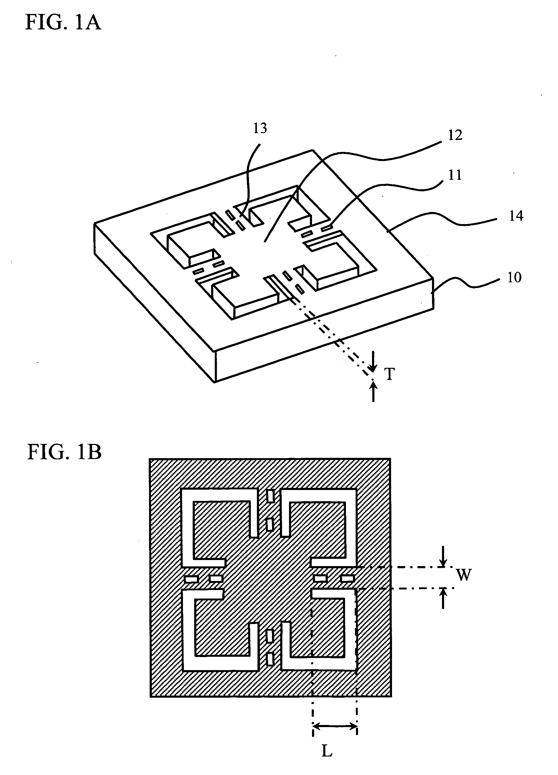
[0035] In order to improve the sensitivity of the inertial sensor, the beam width is made small, the thickness is made thin, the length is made long, and the weight of the weigh is made heavy. In addition, the beams are configured to have holes so that the beams can be distorted easily. However, the beams are distorted by the impact, and the stresses are not evenly distributed. If the holes are provided on a part on which the stress is concentrated, the mechanical strength of the beams is degraded. Therefore, distortion portions are provided in the beams of a sensing portion of the inertial sensor in accordance with the present invention. The distortion portion, such as a concave portion configured to be thin, is arranged effectively and appropriately, and thus, the high sensitivity is obtainable together with the impact resistance.

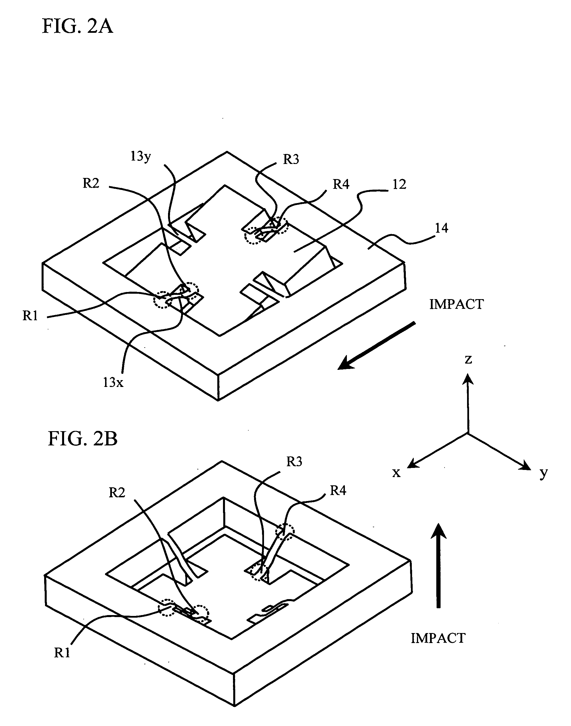
[0036] A description will first be given of the stress generated in the beam when the impact is applied. When the impact is applied to the sensing porti...

second embodiment

[0042] The description has been given of the roots of the sensing portion, which are identical to those of the conventional sensing portion. In view of the improvement of the impact resistance, the mechanical strength of the beam needs to be enhanced in a positive manner. In accordance with a second embodiment of the present invention, the shapes of the roots (edges), on which the stresses are concentrated, in the sensing portion are configured to improve the impact resistance of the sensor.

[0043]FIGS. 4A through 4D illustrate the shapes of the roots in the beam. FIG. 4A is a first example of the roots. FIG. 4B is a second example. FIG. 4C illustrates the conventional shape. The conventional beam has a root shape of a right angle between the weight 12 and the frame 14, as shown in FIG. 3B of the first embodiment of the present invention. However, in accordance with the second embodiment of the present invention, instead of the right angle, the beam 13 is configured to have angles w...

third embodiment

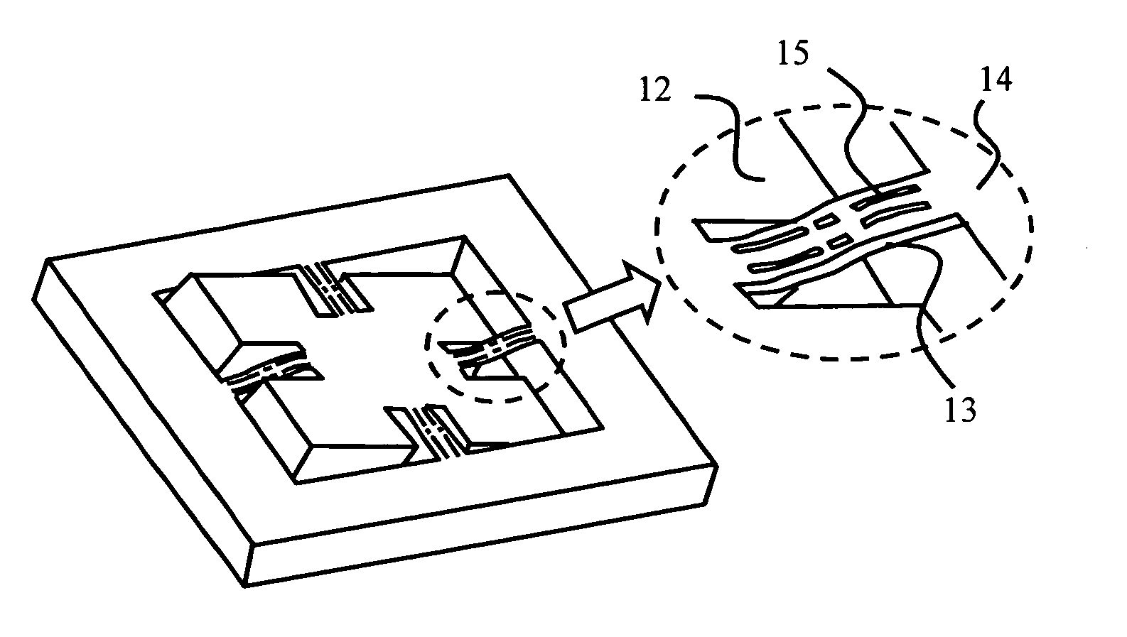
[0047]FIGS. 6A through 6G illustrate examples of the beam shape included in the inertial sensor in accordance with the present invention. The holes 15 are provided symmetrical with respect to a longitudinal direction extending along the center of the beam 13 and another direction perpendicular to the longitudinal direction extending along the center of the beam 13. The piezoelectric resistors 11 are arranged on the beam 13 to avoid the holes 15. The frame 14 includes electrodes 21 and interconnections 22. The piezoelectric resistors 11 are connected with the electrodes 21 and the interconnections 22 and output the changes in the resistance value caused resulting from the movement of the weight 12, to the Wheatstone bridge circuit, not shown.


PUM


Abstract

An inertial sensor comprising a sensing portion having a weight hung by beams extending from a frame, the weight being a movable portion. The beams include distortion portions partially arranged therein, and the distortion portions are arranged to avoid edges on which stresses applied to the beams are concentrated. Roots of the beams are not formed at right angle in connecting to the weights or the frame. The roots of the beams have wider angles. It is thus possible to dissipate areas on which stresses are concentrated and improve the impact resistance without sacrificing the sensor sensitivity. Both high sensor sensitivity and the impact resistance are obtainable in accordance with the present invention.

Description

BACKGROUND OF THE INVENTION [0001] 1. Field of the Invention [0002] This invention generally relates to an inertial sensor such as an acceleration sensor and a gyro sensor, and more particularly, to an inertial sensor having an excellent sensitivity and impact resistance. [0003] 2. Description of the Related Art [0004] In these years, the inertial sensor such as the acceleration sensor and the gyro sensor can realize downsizing, high performance, and low price all together, thanks to the advancement in a fine processing technology to which MEMS (Micro Electro Mechanical System) technique is applied. With this background, the inertial sensor as a MEMS device is expected to be mounted on every device that senses movements for the purpose of car navigation, automotive air-bag control, avoidance of jiggling a camera or camcorder, robot posture control, gesture input recognition for a game, and detection of HDD rotation and shock applied to HDD. A higher sensitivity is demanded by the in...

Claims


Application Information

Patent Timeline
Patent Type & Authority Applications(United States)
IPC IPC(8): G01C19/56G01P1/02G01P15/08G01P15/12G01P15/125
CPCG01P1/023G01P15/18G01P15/123G01P15/0802G01P2015/0842G01C19/00G01C19/56
Inventor ISHIKAWA, HIROSHINAKAMURA, YOSHITAKATOKUNAGA, HIROSHINAGATA, KENJI
Owner FUJITSU MEDIA DEVICES
Why Eureka
Try Eureka