Micromechanical heat conductivity sensor having a porous cover

a micro-mechanical and thermal conductivity sensor technology, applied in the field of micro-mechanical thermal conductivity sensors, can solve the problems of falsification of the actual thermal conductivity value, short response time (time constant) of the miniaturized sensor, and general only achievable results

Inactive Publication Date: 2005-02-03
ROBERT BOSCH GMBH
View PDF36 Cites 28 Cited by
  • Summary
  • Abstract
  • Description
  • Claims
  • Application Information

AI Technical Summary

Benefits of technology

An object of the present invention is to overcome the disadvantages of the conventional micromechanical thermal-conductivity. In particular, a universally applicable

Problems solved by technology

Moreover, the miniaturized sensors possess short response times (time constants) which generally can only be achieved by the acceptance of a forced traversal with the measuring gas, i.e., a flow dependency, in the case of conventional sensors.
In the last analysis, however, this makes universal use impossible.
A fundamental problem when measuring the thermal conductivity of a surrounding gas is the heat transfer caused by convection of the gas, accompanied by a falsification of the actual thermal-conductivity value.
It may be that a forced traversal of the thermal-conductivity sensor with the gas to be measured is definitely desired in order to permit a rapid gas exchange and therefore short response times; however, for micromechanical thermal-conductivi

Method used


Image

  • Micromechanical heat conductivity sensor having a porous cover
  • Micromechanical heat conductivity sensor having a porous cover
  • Micromechanical heat conductivity sensor having a porous cover

Examples


Embodiment Construction

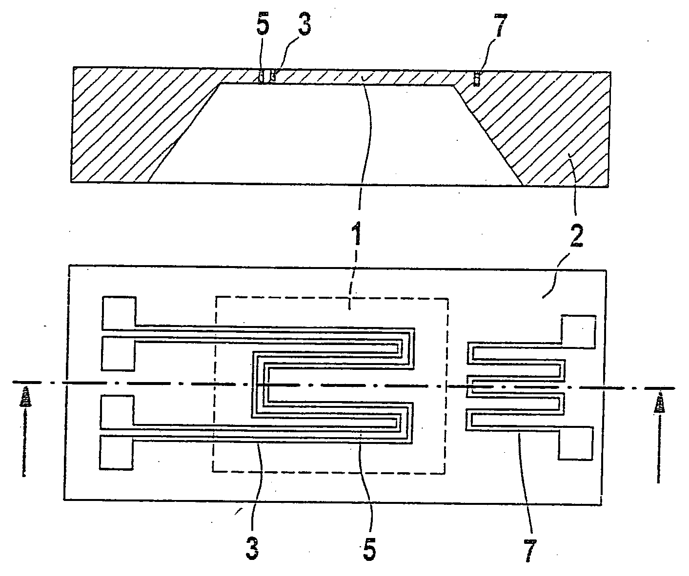
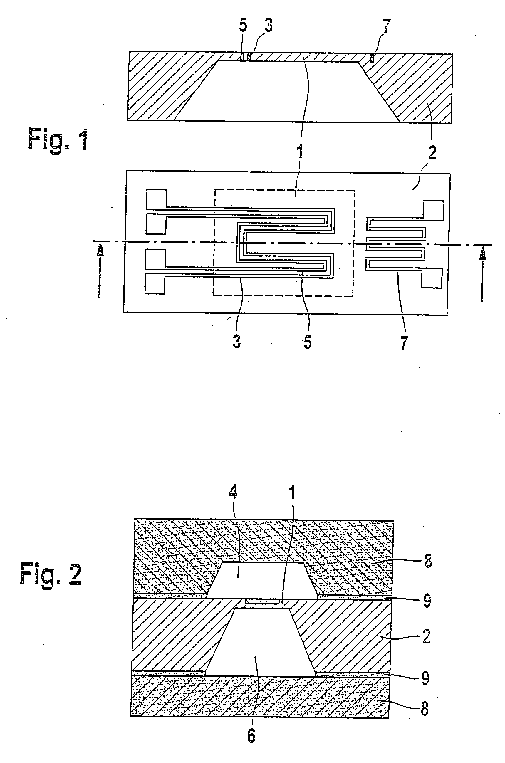
As the lower part of FIG. 1 shows, in a typical conventional micromechanical thermal-conductivity sensor, a heating element (resistance element) 3 in the form of a Pt-resistance wire and a temperature-dependent electrical resistor 5 for detecting diaphragm temperature TM are arranged in a meander form on silicon base plate 2 and diaphragm 1, respectively. Located outside of diaphragm 1 is a further temperature-dependent electrical resistor 7 for detecting ambient temperature TU. Base plate 2, together with the applied electrical structures, forms a silicon sensor chip for measuring the thermal conductivity. In the upper part of FIG. 1, it can be seen that diaphragm 1 is formed as a recess in base plate 2.

To measure the thermal conductivity of the surrounding gas or gas mixture, for example, the heating power of the heating element needed to keep the difference between TM and TU constant is determined. Because of the small mass of the thin diaphragm and the materials applied there...


PUM


Abstract

A micromechanical thermal-conductivity sensor is provided which includes a thermally insulated diaphragm formed by a recess in a base plate exhibiting poor thermal conductivity. At least one heating element is applied on the diaphragm, at least one temperature-dependent electrical resistor is applied on the diaphragm for measuring the temperature of the diaphragm, as well as at least one further temperature-dependent electrical resistor is applied outside of the diaphragm on the base plate for measuring the ambient temperature. On one or both of its sides, the diaphragm is covered by a porous cover plate permitting gas exchange by diffusion, a cavity being left open between the diaphragm and the porous cover plate.

Description

FIELD OF THE INVENTION The present invention relates to a micromechanical thermal-conductivity sensor. In particular, it relates to a micromechanical thermal-conductivity sensor which includes a thermally insulated diaphragm formed by a recess in a base plate exhibiting poor thermal conductivity, at least one heating element applied on the diaphragm, at least one temperature-dependent electrical resistor applied on the diaphragm for measuring the diaphragm temperature (TM), as well as at least one further temperature-dependent electrical resistor, applied outside the diaphragm on the base plate, for measuring the ambient temperature (TU). The present invention also relates to a method for producing the thermal-conductivity sensor, as well as its use. BACKGROUND INFORMATION The measurement of thermal conductivity is used frequently for analyzing gases, particularly for the quantitative analysis of two-component gas mixtures. In principle, it holds true that the thermal conductivit...

Claims


Application Information

Patent Timeline
IPC IPC(8): G01N25/18G01N27/18
CPCG01N27/18G01N25/18
Inventor ARNDT, MICHAELLORENZ, GERD
Owner ROBERT BOSCH GMBH
Why Eureka
Try Eureka