Tubing hanger running tool and subsea test tree control system

a technology of test tree and running tool, which is applied in the direction of fluid removal, sealing/packing, and well accessories, etc., can solve the problems of requiring expensive equipment rental, cumbersome process of running sstt, and time-consuming for well operators, so as to reduce the time of rig, reduce the effect of control umbilical, and enhance safety

a technology of test tree and running tool, which is applied in the direction of fluid removal, sealing/packing, and well accessories, etc., can solve the problems of requiring expensive equipment rental, cumbersome process of running sstt, and time-consuming for well operators, so as to reduce the time of rig, reduce the effect of control umbilical, and enhance safety

US20050217845A1Inactive Publication Date: 2005-10-06MCGUIRE LINDELL V

Image

  • Tubing hanger running tool and subsea test tree control system
  • Tubing hanger running tool and subsea test tree control system
  • Tubing hanger running tool and subsea test tree control system

Examples


Embodiment Construction

[0020] The features and other details of the invention will now be more particularly described with reference to the accompanying drawings. It will be understood that particular embodiments described herein are shown by way of illustration and not as limitations of the invention. The principal features of this invention can be employed in various embodiments without departing from the scope of the invention.

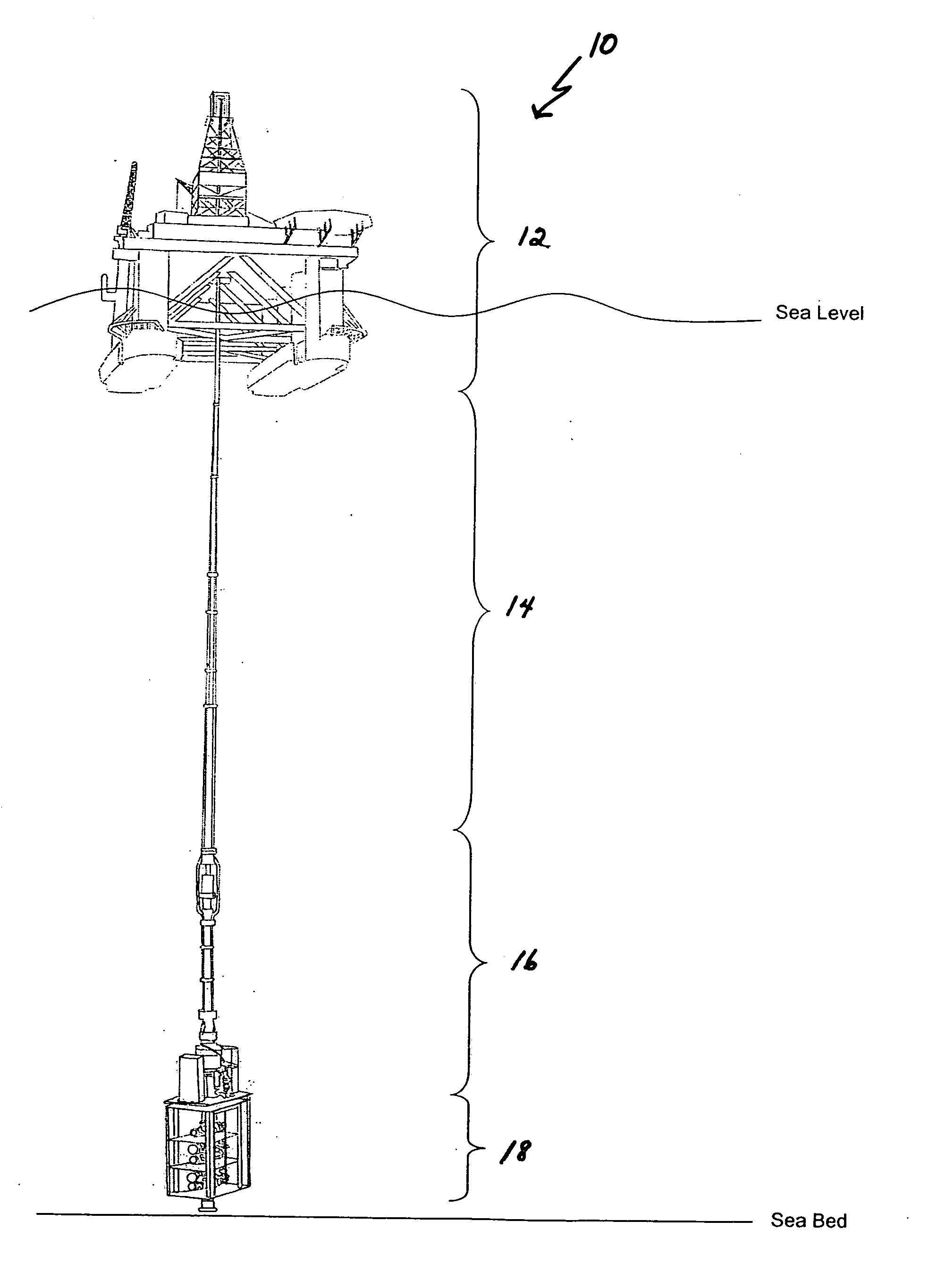
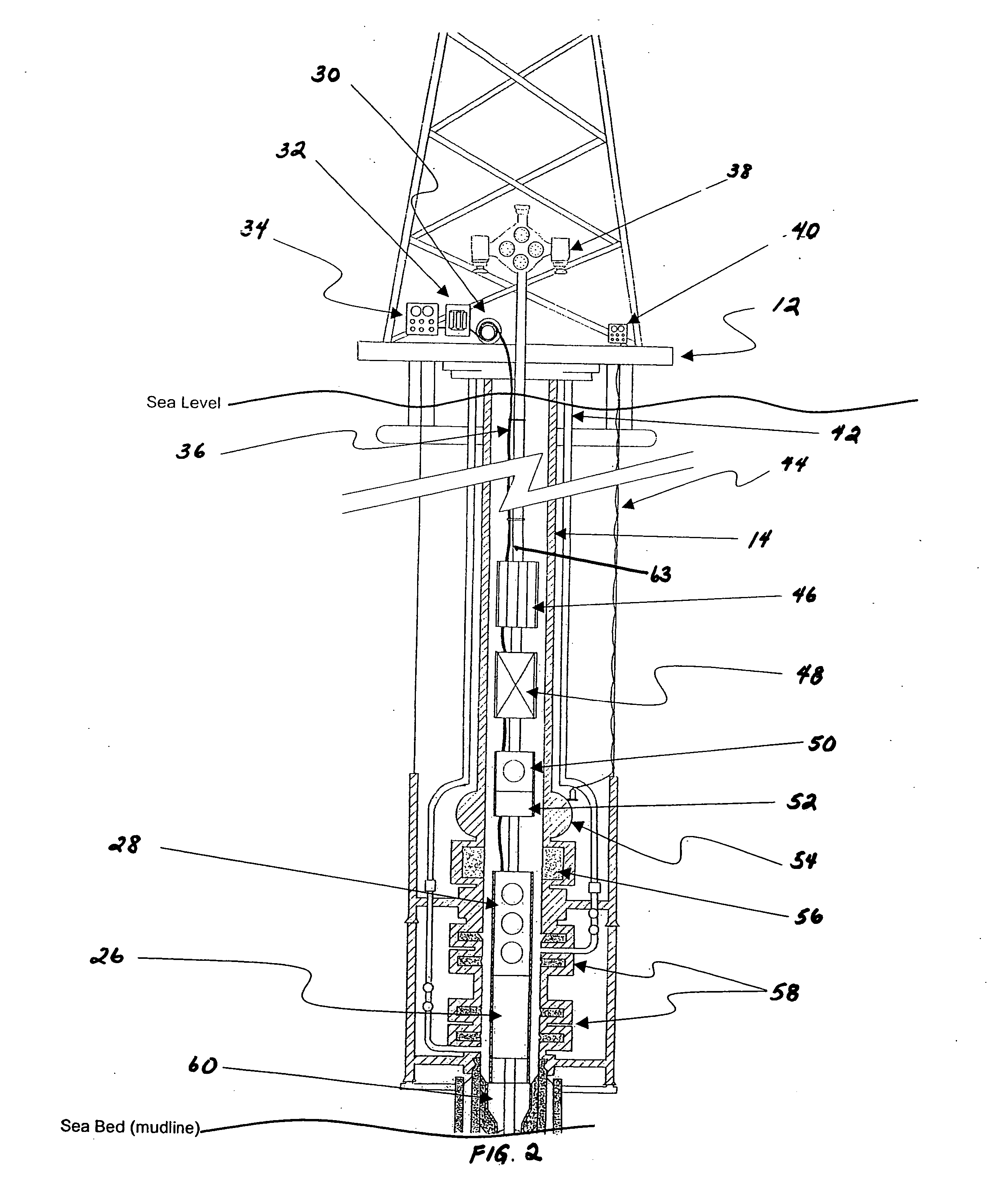
[0021] Embodiments of the invention are related to subsea well technology, and specifically to an improved tubing hanger running tool (THRT) and subsea test tree (SSTT). Embodiments of the invention eliminate a control umbilical and associated hydraulic power pack, as well as associated reel and control panel. Embodiments of the invention use a choke and / or kill line of the blowout preventer system (BOP) to supply hydraulic power. Further, embodiments of the invention use battery powered shuttle valves to direct hydraulic fluid through internal piping and ports to perform many f...


PUM


Abstract

A system for providing power to elements down-hole in a subsea well includes a control pod having at least one shuttle valve, a down-hole hydraulically-actuated device having at least one internal porting mechanism in fluid communication with the at least one shuttle valve, a blowout preventer stack connected to the down-hole device, the blowout preventer stack including a first ram and a second ram, and a choke line in fluid communication with an area between the first ram and the second ram. The at least one shuttle valve controls distribution of hydraulic pressure applied through the choke line to the internal porting mechanism for selective distribution of power to the hydraulically-actuated device.

Description

RELATED APPLICATIONS [0001] This application claims priority to U.S. Provisional Application No. 60 / 558,078, entitled, “Subsea Test Tree,” filed Mar. 30, 2004, and to U.S. Provisional Application No. 60 / 580,474, entitled, “Tools for Completing Subsea Wells,” filed Jun. 17, 2004, each of which is herein incorporated by reference.FIELD OF THE INVENTION [0002] This invention relates to subsea well technology, and specifically to an improved tubing hanger running tool and subsea test tree control system and method of controlling hydraulic / electric tools or equipment used during drilling, testing or completion of a subsea well. BACKGROUND OF THE INVENTION [0003] A subsea well constructed for producing hydrocarbons consists of a series of concentric drilled and cased bores. The casings typically include sections of threaded and coupled pipes screwed together. The casings are run into the well bore, suspended (landed) in a wellhead attached to the first casing string (referred to as conduc...

Claims


Application Information

Patent Timeline
06 Oct 2005
Publication
US20050217845A1
IPC
E21B29/12; E21B33/035; E21B33/12; E21B34/04
CPC
E21B34/045; E21B33/0355
Inventors
MCGUIRE, LINDELL V.