Engine mount

a technology for engine mounts and mounting brackets, which is applied in the direction of machine supports, shock absorbers, jet propulsion mountings, etc., can solve the problems of inability to adequately attenuate vibration in the left-right direction, increase the cost of engine mounts, and install separate rubber stops, so as to facilitate the attachment of the engine mount to the engine side or the body side, and the configuration is simple and easy to achieve. , the effect of occupying the least spa

Inactive Publication Date: 2005-10-06
SUMITOMO RIKO CO LTD
View PDF6 Cites 15 Cited by
  • Summary
  • Abstract
  • Description
  • Claims
  • Application Information

AI Technical Summary

Benefits of technology

[0007] It is therefore an object of the present invention to provide an engine mount wherein, by means of increasing spring constant in the axial direction, vibration in the left-right direction can be attenuated to a sufficient extent even where the mounting is installed with its axial direction coincident with the left-right direction of the vehicle, and wherein spring constant in the left-right direction is increased without changing the spring constant ratio in the vehicle vertical and front-back directions, affording case of tuning of the spring constant in three directions.
[0011] Further, by providing the main rubber elastic body with a hollow portion that extends from the second axial end to the first end, with the distal end thereof extending out into the interior of the side rubber elastic body, it is possible for the spring constant in the left-right direction (axial direction) of the rubber elastic body to exert no effect on spring constant in vertical and front-back directions which are axis-perpendicular directions, or in other words, to establish it independently of spring constant in the vertical and front-back directions. That is, it becomes easy to tune the ratio of spring constants in three directions, namely, the vertical, left-right, and front-back directions. As a result, in the present invention, spring constants in the vertical, left-right, and front-back directions of the engine mount can be established so as to be properly matched with the vibration characteristics of the vehicle. Also, by providing a hollow portion in the main rubber elastic body, compressing deformation in the vertical direction of the main rubber elastic body can be absorbed by the hollow portion, permitting uniform deformation of the main rubber elastic body.
[0013] Preferably, in the engine mount described above, the inner fitting is of cylindrical shape, attached to a component on the engine side or a component on the body side by means of a mounting member of rod form which is passed through a bore of the inner fitting. By employing an inner fitting of cylindrical shape and attaching the inner fitting to an engine component or body component by means of a bolt or other fastener passed through the bore of the inner fitting in this way, the engine mount can be given a simple configuration that occupies the least space.
[0014] Yet preferably, in the engine mount described above, the outer fitting is integrally formed with an engine-side bracket or with an body-side bracket. By means of integrally forming the outer fitting with the engine-side bracket or with the body-side bracket, attachment of the engine mount to the engine side or body side is facilitated, reducing the labor entailed in the mounting procedure.
[0015] According to the present invention, by elastically connecting the first flange of the inner fitting with the second flange of the outer fitting, spring characteristics in the axial direction are increased appreciably. As a result, with the engine mount installed on the vehicle with its axial direction facing in the left-right direction of the vehicle, vibration in the left-right direction of the vehicle can be attenuated sufficiently. Additionally, by providing the main rubber elastic body with a hollow portion that extends from the second axial end towards the first end, with the distal end thereof situated within the side rubber elastic body, it is possible for the spring constant in the left-right direction (axial direction) of the rubber elastic body to be established independently of spring constant in the vertical and front-back directions. As a result, spring constant in the vertical, front-back, and left-right directions of the engine mount can be set appropriately matched to vibration characteristics of the vehicle. Also, by providing a hollow portion in the main rubber elastic body, compressing deformation in the vertical direction of the main rubber elastic body is absorbed by the hollow portion, increasing the durability of the main rubber elastic body.

Problems solved by technology

In the event that the engine mount is positioned with the axial direction facing in the left-right direction of the vehicle, there arises problem of inability to adequate attenuate vibration in the left-right direction due to the low spring constant in the axial direction.
However, it is difficult to install separate rubber stops on the two axial sides, making the engine mount more expensive.

Method used


Image

  • Engine mount
  • Engine mount
  • Engine mount

Examples


first embodiment

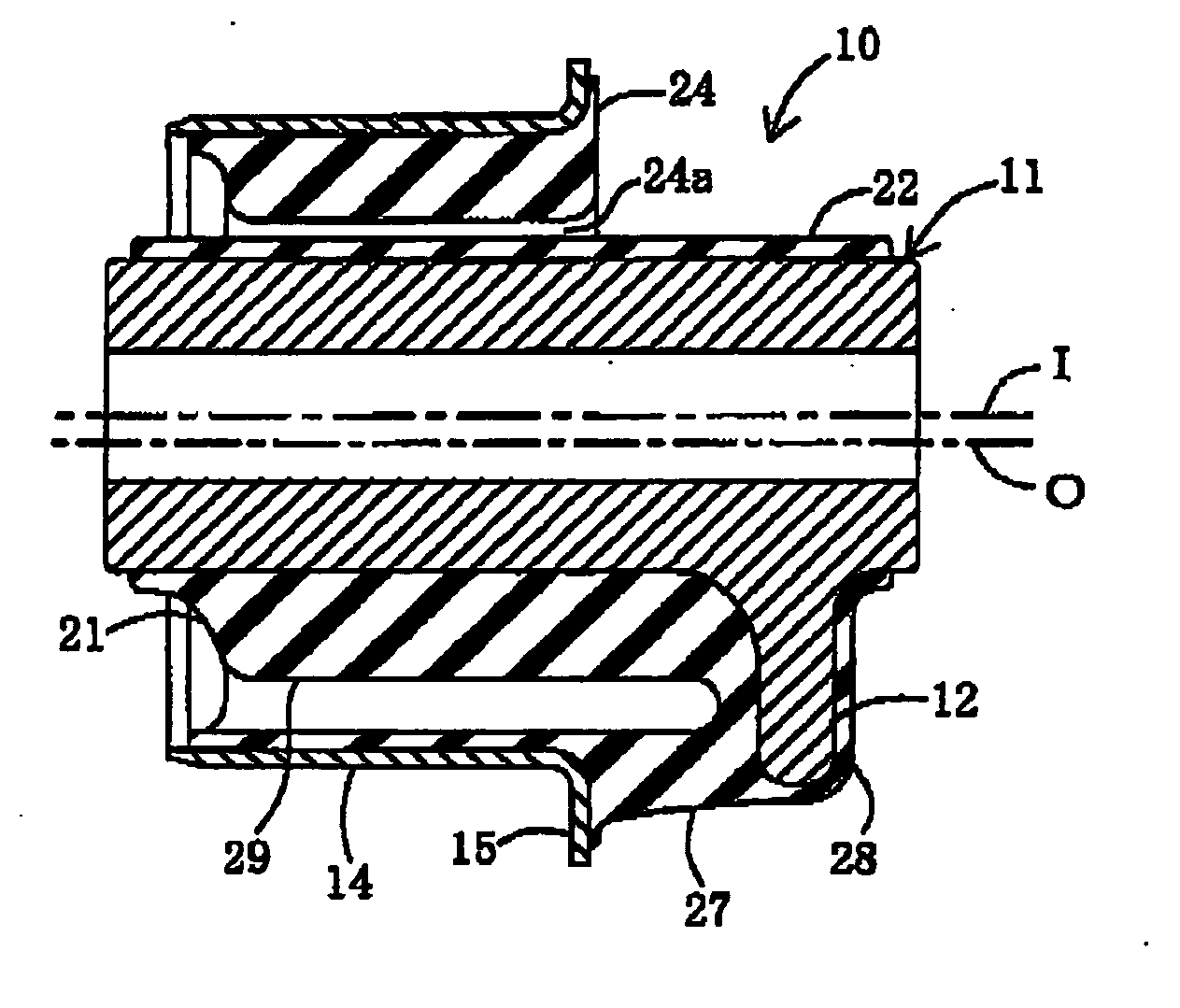
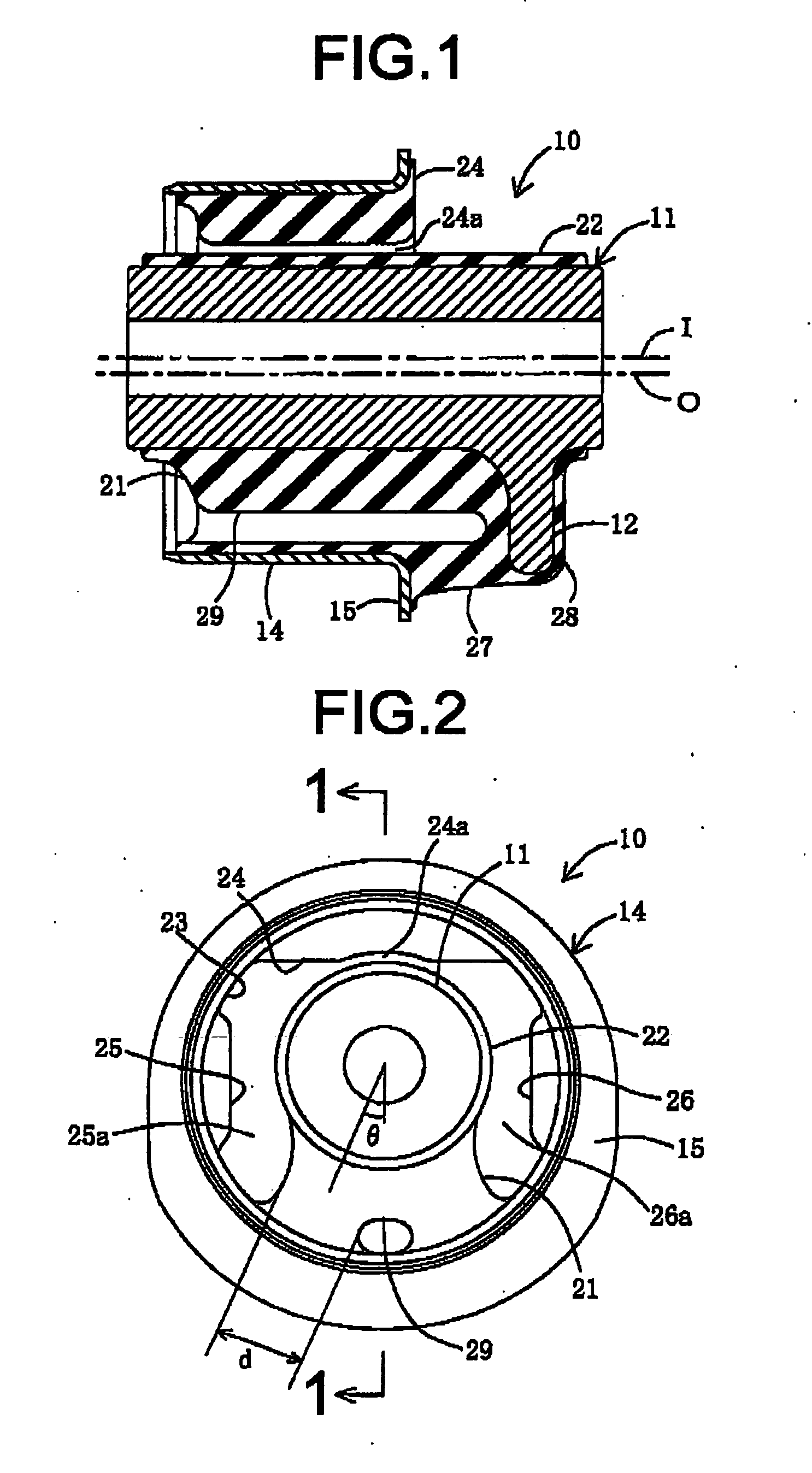
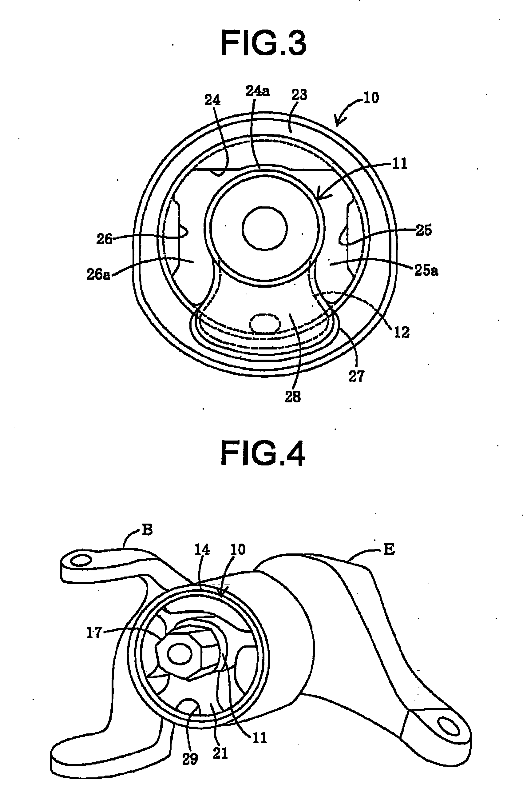
[0028] Following is a description of currently preferred embodiment of the invention, with reference to the accompanying drawings. FIGS. 1-3 are, respectively, a sectional view, a left side view, and a right side view of an engine mount 10 which is a vibration damping device installed between a component on the engine side and a component on the body side of a vehicle. FIG. 4 is a perspective view showing the engine mount installed on a vehicle.

[0029] The engine mount 10 comprises a round cylindrical inner fitting 11 having a first flange 12 that extends diametrically outward from a portion of the outside circumferential face at a first axial end. A cylindrical outer fitting 14 disposed surrounding the inner fitting 11 from outside in the diametrical direction and positioned between the two axial ends thereof, and having at a first axial end an annular second flange 15 that extends outwardly in the diametrical direction and is positioned in juxtaposition to but spaced apart from th...

second embodiment

[0050] By providing the main rubber elastic body 51 with the hollow portion 59, compressing deformation in the vertical direction of the main rubber elastic body 51 is absorbed by the hollow portion 59, permitting uniform deformation of the main rubber elastic body 51, as a result of which the durability of the rubber elastic body 51 is increased. Additionally, in the engine mount 30 described above, since the hollow portion 59 is situated at a medial location in the circumferential direction of the main rubber elastic body 51, the main rubber elastic body 51 is bifurcated equally to either side by means of the hollow portion 59. Thus, spring characteristics in the axis-perpendicular directions are established uniformly by means of the main rubber elastic body 51, and the vibration-attenuating function of the main rubber elastic body 51 is exhibited properly. Also, in the second embodiment, by having the outer fitting 36 double as the body-side bracket, installation of the engine mo...


PUM


Abstract

An engine mount including: an inner fitting having a first flange at a first axial end thereof; a cylindrical outer fitting having at a first axial end a second flange extending outwardly in the axis-perpendicular direction and positioned in opposition to but spaced apart from the first flange portion in an axial direction; a side rubber elastic body elastically connecting the first and second flanges; a main rubber elastic body elastically connect the inner fitting and the outer fitting in a direction of axial elongation of the side portion rubber elastic body; and a hollow portion extending from a second axial end toward a first axial end of the main rubber elastic body with a distal and thereof reaching an interior of the side rubber elastic body, thereby bifurcating the main rubber elastic body at an inside circumferential face of the outer fitting. The engine mount is positioned with the axial direction facing a left-right direction of the vehicle.

Description

INCORPORATED BY REFERENCE [0001] The disclosure of Japanese Patent Application No. 2004-098120 filed on Mar. 30, 2004 including the specification, drawings and abstract is incorporated heroin by reference in its entirety. BACKGROUND OF THE INVENTION [0002] 1. Field of the Invention [0003] The present invention relates to an engine mount having an inner and an outer metal fitting elastically connected by a rubber elastic body, wherein the inner and outer fittings attached to a component on the engine side and a component on the body-side, to reduce engine vibration. [0004] 2. Description of the Related Art [0005] Known engine mounts of this kind for use in automotive vehicles include one with a design such as that taught for example in JP-A-10-47402, which comprises a round cylindrical inner member, a cylindrical outer member disposed coaxially with the inner member and spaced outwardly apart therefrom, and a pair of rubber elastic arms extending from both diametrical sides of the in...

Claims


Application Information

Patent Timeline
Patent Type & Authority Applications(United States)
IPC IPC(8): B60K5/12F16F1/38F16F1/387F16F5/00F16F15/08
CPCF16F1/387F16F1/3863B60K5/12B60K5/1266F16F1/3807F16F1/3835
Inventor ENDO, MASAMI
Owner SUMITOMO RIKO CO LTD
Why Eureka
Try Eureka