Comb-line filter

a comb-line filter and filter body technology, applied in the direction of waveguide devices, basic electric elements, electric apparatus, etc., can solve the problems of filter not being able to effectively dissipate heat, plastic filters providing unsatisfactory power handling, and heavy weigh

Inactive Publication Date: 2005-10-06
MITEC TELECOM
View PDF21 Cites 21 Cited by
  • Summary
  • Abstract
  • Description
  • Claims
  • Application Information

AI Technical Summary

Problems solved by technology

A disadvantage associated with conventional metal filters is that they are heavy in weight, and are expensive to produce and transport.
However, a disadvantage associated with plastic filters is that the plastic material is a poor thermal conductor, thereby rendering the filter unable to effectively dissipate the heat caused by electrical current flow in the conductive film or caused by the insertion loss of the filter.
Since it is generally accepted that an important factor in the power handling of a filter is the filter's heat dissipation arrangement, such plastic filters provide unsatisfactory power handling.

Method used


Image

  • Comb-line filter
  • Comb-line filter
  • Comb-line filter

Examples


second embodiment 200

Second Embodiment 200

[0048] Shown in FIG. 5 is an exploded view of a comb-line filter 200 in accordance with a second non-limiting example of implementation of the present invention. Similarly to the comb-line filter 100 as described above with respect to FIGS. 1 and 2, comb-line filter 200 includes a housing 202 and a plurality of resonators 204. The housing 202 includes a first portion 206 and a second portion 208. The first portion 206 is made of a dielectric material and the second portion 208 is made of a conductive material. As shown, the plurality of resonators 204 are attached to the second portion 208 of the housing 202, which is the portion made of a conductive material.

[0049] In this embodiment, the comb-line filter 200 includes a plurality of tuning screws 210 for adjusting the response characteristics of the comb-line filter, and a plurality of coupling screws 212 for further adjusting the response characteristics of the comb-line filter 100. The coupling screws 212 ar...

third embodiment 300

Third Embodiment 300

[0053] Shown in FIG. 6 is an exploded view of a comb-line filter 300 in accordance with a third non-limiting example of implementation of the present invention. Comb-line filter 300 includes a housing 302 and a plurality of resonators 304.

[0054] The housing 302 includes a first portion 306 and a second portion 308. In this non-limiting embodiment, the second portion 308 comprises two parts, namely a first part 314 and a second part 316. In a preferred embodiment, the first portion 306 is made of a dielectric material and both the first part 314 and the second part 316 of the second portion 308 are made of a conductive material.

[0055] The first portion 306 and the second portion 308 are adapted to be attached together, so as to define an interior chamber. When attached together, the first portion 306 of the housing 302 is sandwiched between the first part 314 and the second part 316 of the second portion 308 of the housing 302. As such, the first part 314 of the...


PUM


Abstract

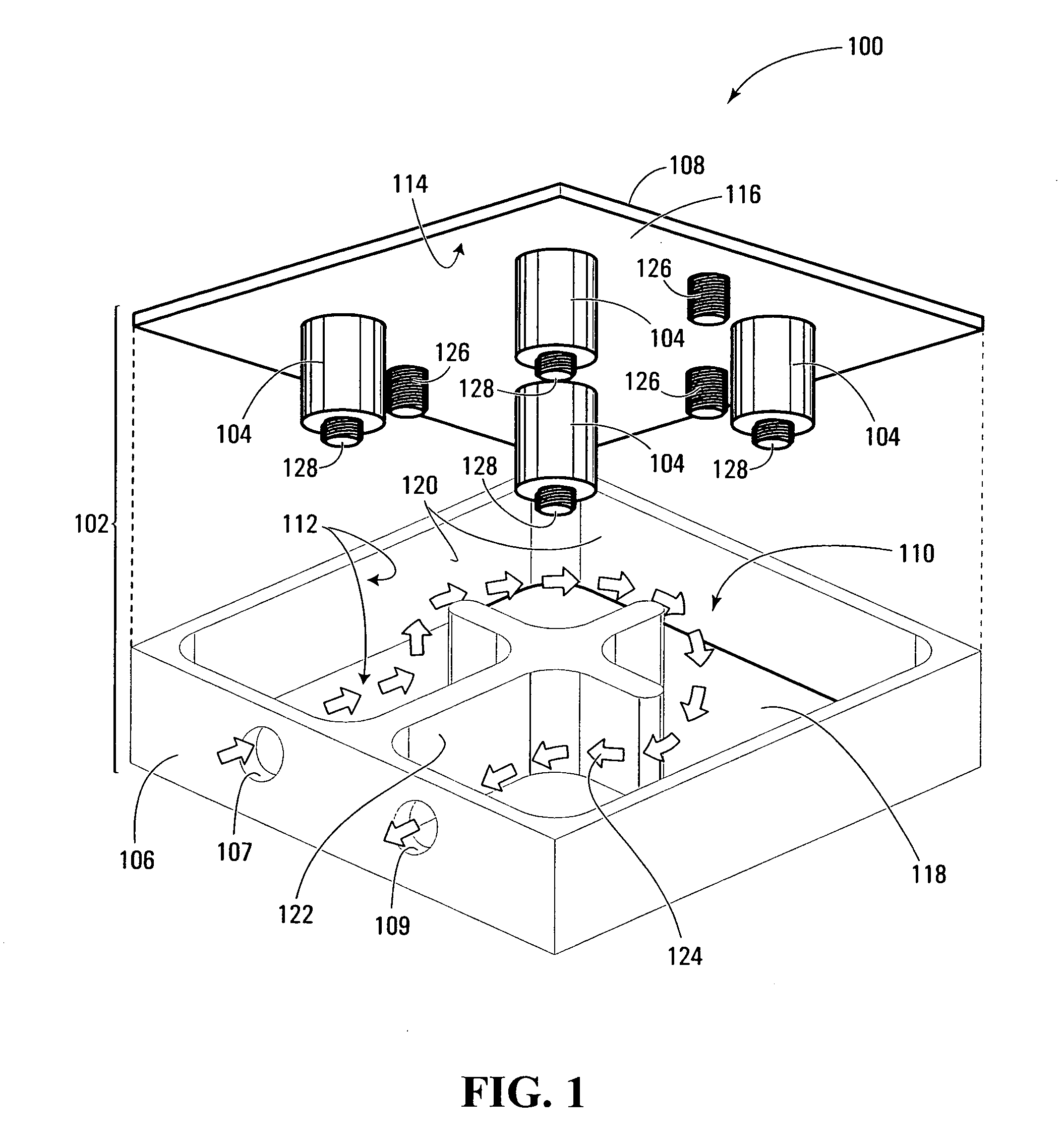
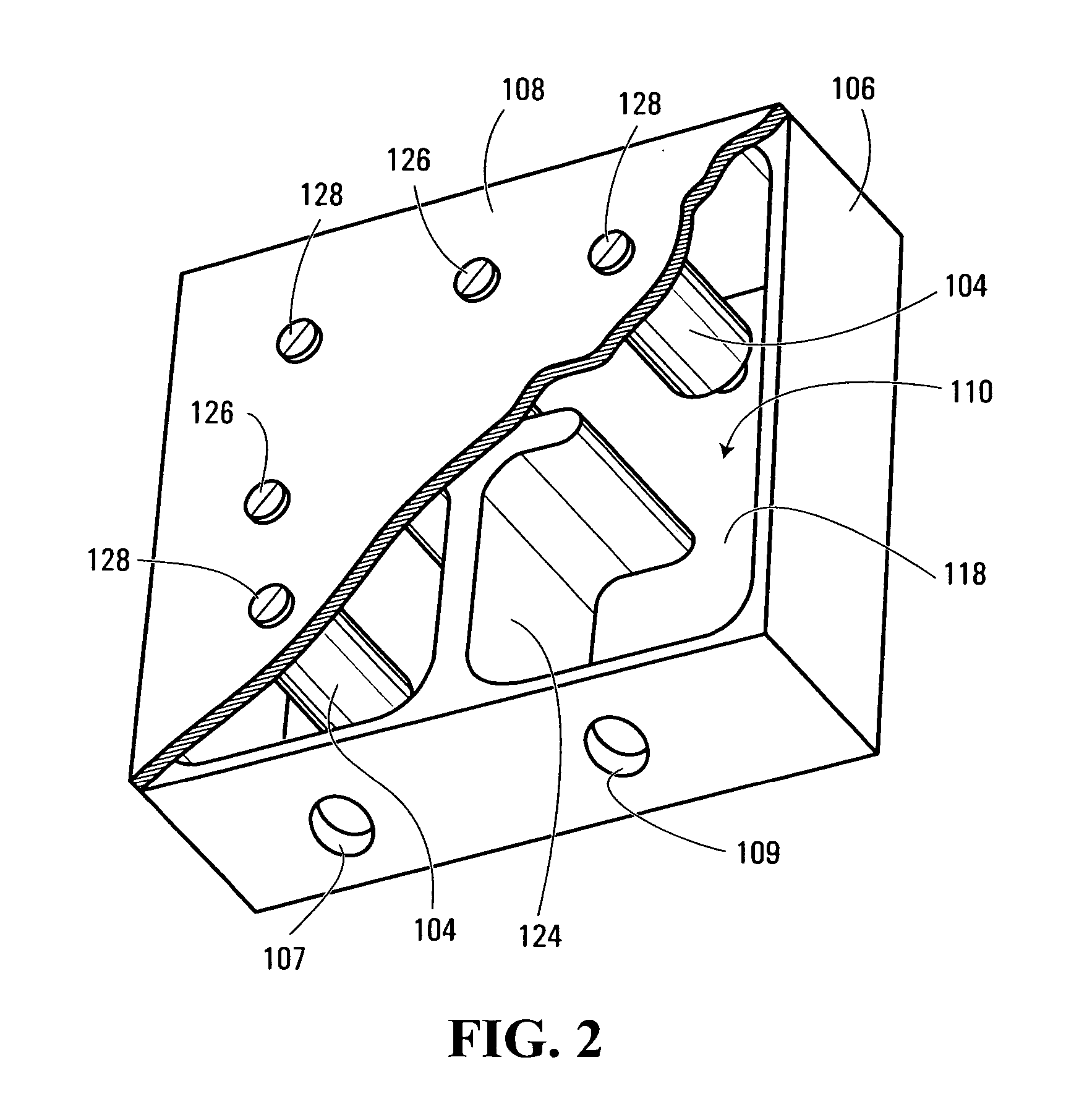
A comb-line filter and method of manufacturing the comb-line filter. The comb-line filter comprising a housing and at least one resonator. The housing comprises a first portion and a second portion, wherein the first portion is made of a dielectric material and the second portion is made of a conductive material. The first portion and the second portion are adapted for being attached together so as to define an interior chamber for conducting signals. The at least one resonator is attached to the second portion, and is adapted for extending within the interior chamber when the first portion and the second portion are attached. Comb-line filters in accordance with the present invention provide relatively low-cost and light-weight composite material comb-line filters.

Description

FIELD OF THE INVENTION [0001] The present invention relates generally to the field of comb-line filters, and more specifically to comb-line filters that are made of a combination of dielectric and conductive materials. BACKGROUND [0002] Comb-line filters for filtering wireless signals are known in the art. Typically, comb-line filters include a metal housing that includes a base portion and a lid, with a set of resonators integrally molded or bolted on to the base portion. During use, wireless / microwave signals enter the filter housing and follow a signal pathway around / through the resonators. Depending on the position and configuration of the resonators, the frequency response of the filter can be tailored to suit specific operational needs. [0003] A disadvantage associated with conventional metal filters is that they are heavy in weight, and are expensive to produce and transport. [0004] One method aimed at overcoming some of the disadvantages of the metal filters described above,...

Claims


Application Information

Patent Timeline
Patent Type & Authority Applications(United States)
IPC IPC(8): H01P1/205H01P11/00
CPCH01P1/2053
Inventor KUMAR, PAVANRICHARD, ROLANDROBERGE, JEAN-MARC
Owner MITEC TELECOM
Why Eureka
Try Eureka