Method and apparatus for analysis of digital video images

a digital video and image technology, applied in the field of digital video image analysis methods and apparatuses, can solve problems such as errors in compression, transmission, color space conversion, and transmission encoding, and achieve the effects of high usefulness, convenient and versatil

Active Publication Date: 2005-10-06
HBC SOLUTIONS
View PDF19 Cites 14 Cited by
  • Summary
  • Abstract
  • Description
  • Claims
  • Application Information

AI Technical Summary

Benefits of technology

[0017] An object of the invention is to mediate the foregoing conflicting interests in a digital video test apparatus. That is, the invention advantageously serves important interests in versatility versus convenience, focus on spatial detail versus a larger view, time capture versus flow, and numeric versus visual presentations. Preferably, this is accomplished using digital data processing, display driver and display presentation apparatus with certain automatic and certain user selection modes, including the selection of particular outputs to be presented at a given time. The result is a device that is versatile, convenient and highly useful in video production environments and the like.

Problems solved by technology

There can be issues respecting encoding for transmission and decoding, such as errors that arise in compression, transmission, and color space conversions.
There are issues as to correct synchronization and timing.
On the data collection side, it is possible, for example, that isolated pixels in a picture are erroneous or out of range.
In a video signal that is changing many times per second, an error in a particular frame can be difficult to find.
Errors or other subjects of analysis may present numeric issues or visual issues.

Method used


Image

  • Method and apparatus for analysis of digital video images
  • Method and apparatus for analysis of digital video images
  • Method and apparatus for analysis of digital video images

Examples


Embodiment Construction

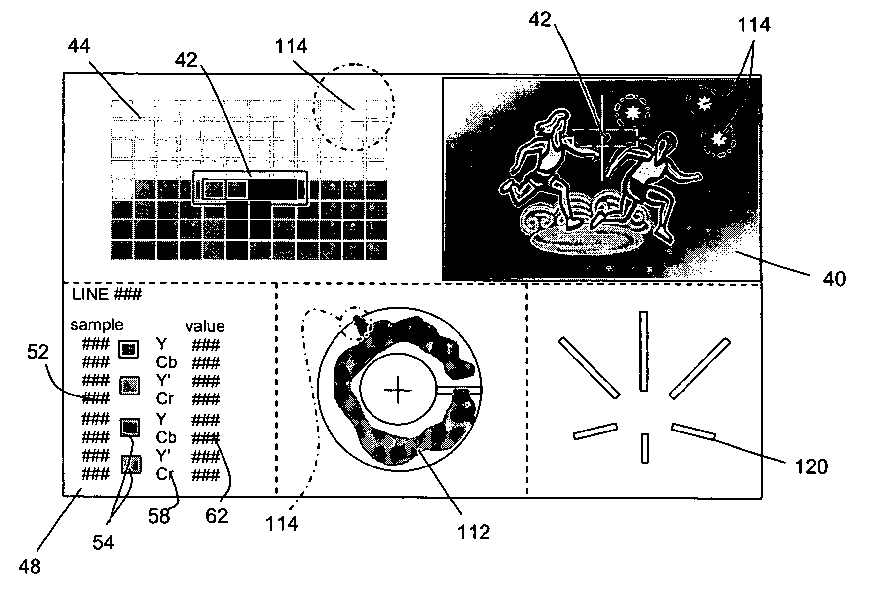
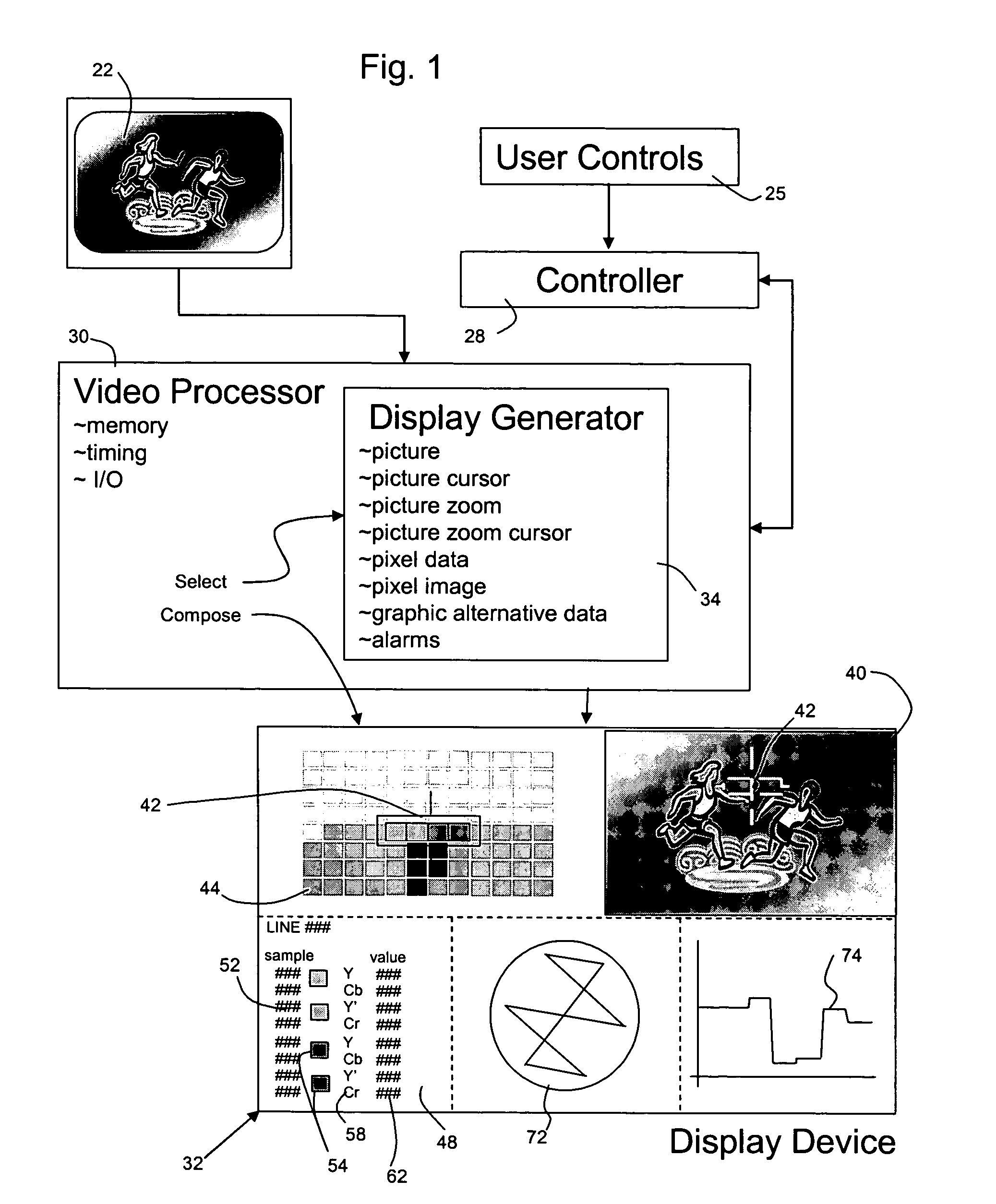
[0029] Referring to the block diagram in FIG. 1, a multi-format display device and associated method are shown, particularly for application to video production and test uses. The device and method are arranged to facilitate the analysis of a stored or active (e.g., live) video signal, using different information display formats at different areas of a display. According to the invention these area display a version of the incoming video signal, a relocatable zoom area of the incoming video signal associated with a cursor position, a tabular information display showing digital sample values that contributed to the video at the cursor as well as corresponding color swatches, and can further include certain graphic plots representing time, amplitude, and color-space value plots that demonstrate aspects of the video signal.

[0030] In FIG. 1, the input video signal 22 is represented by an image box. The invention is applicable to a digital video signal, but the original input signal 22 ...


PUM


Abstract

A multi-format display device for video production and testing presents a video signal in three or more distinct ways at different areas of a display, to facilitate analysis of video data for discrete areas within the video picture. A video processor produces a complete picture from the input signal on a limited part of the device display area, such as a quadrant of a digitally controlled standard display. At another limited part, preferably on the same display, a picture zoom is presented, showing a visual enlargement of a subpart of the picture around a cursor position, preferably large enough to point out individual pixels or data samples. A third part of the display presents a tabular form of specific pixel numeric data for one or more pixels at the cursor, and also produces a color swatch corresponding to the pixel data values. Graphic plots of picture data, audio and other associated information can be placed in remaining areas. The controller and video processor are operable to accept pixel selection criteria, to identify pixels in the display that meet the criteria, and to scrutinize the selected pixels in sequence, subject to manual selection override.

Description

FIELD OF THE INVENTION [0001] The invention relates to test equipment apparatus and methods for use in analyzing digital image data. The data can represent successive frames in a live or recorded video program and frames, portions of frames and individual pixels can be captured and presented. PRIOR ART [0002] Certain known video test devices are capable of generating several different sorts of test images, and can present one of plural selectable test images on a display screen, or two or more of a set of selectable test images, at the same time. [0003] A simultaneous display may include a video picture image presented in a window area less than the full area of the screen, and a simultaneously displayed graph of information that relates to the same video picture. For example, a reduced-size image of the picture may be presented in one quadrant, while simultaneously showing in another quadrant a graph of composite video signal voltage amplitude versus time, thus plotting amplitude o...

Claims


Application Information

Patent Timeline
Patent Type & Authority Applications(United States)
IPC IPC(8): G09G5/00
CPCH04N17/02
Inventor HOLLOWBUSH, RICHARD R.DESCHAMP, JOSEPHGUERRERO, DAVID R.MAUGER, RANDY A.ZWIEBEL, ROBERT C.
Owner HBC SOLUTIONS
Why Eureka
Try Eureka