
Processing architecture for automatic image registration

a processing architecture and image technology, applied in image data processing, scene recognition, instruments, etc., can solve the problems of producing uncertainty in the actual orientation and size of the sensed area or footprint, and achieve the effect of significantly different perspectives of the scene, high accuracy and high precision

Inactive Publication Date: 2005-10-06
THE BOEING CO
View PDF22 Cites 88 Cited by
  • Summary
  • Abstract
  • Description
  • Claims
  • Application Information

AI Technical Summary

Benefits of technology

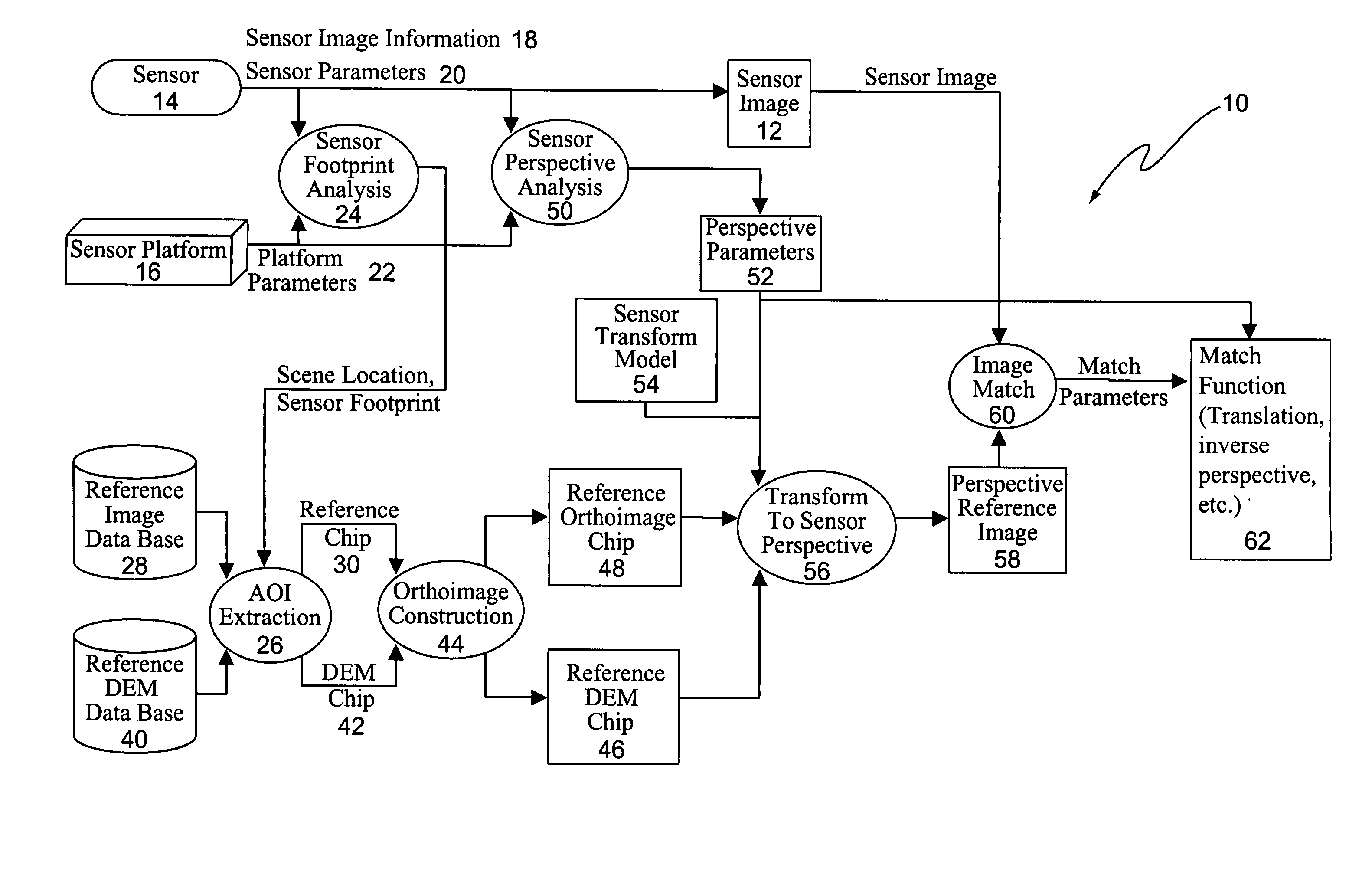
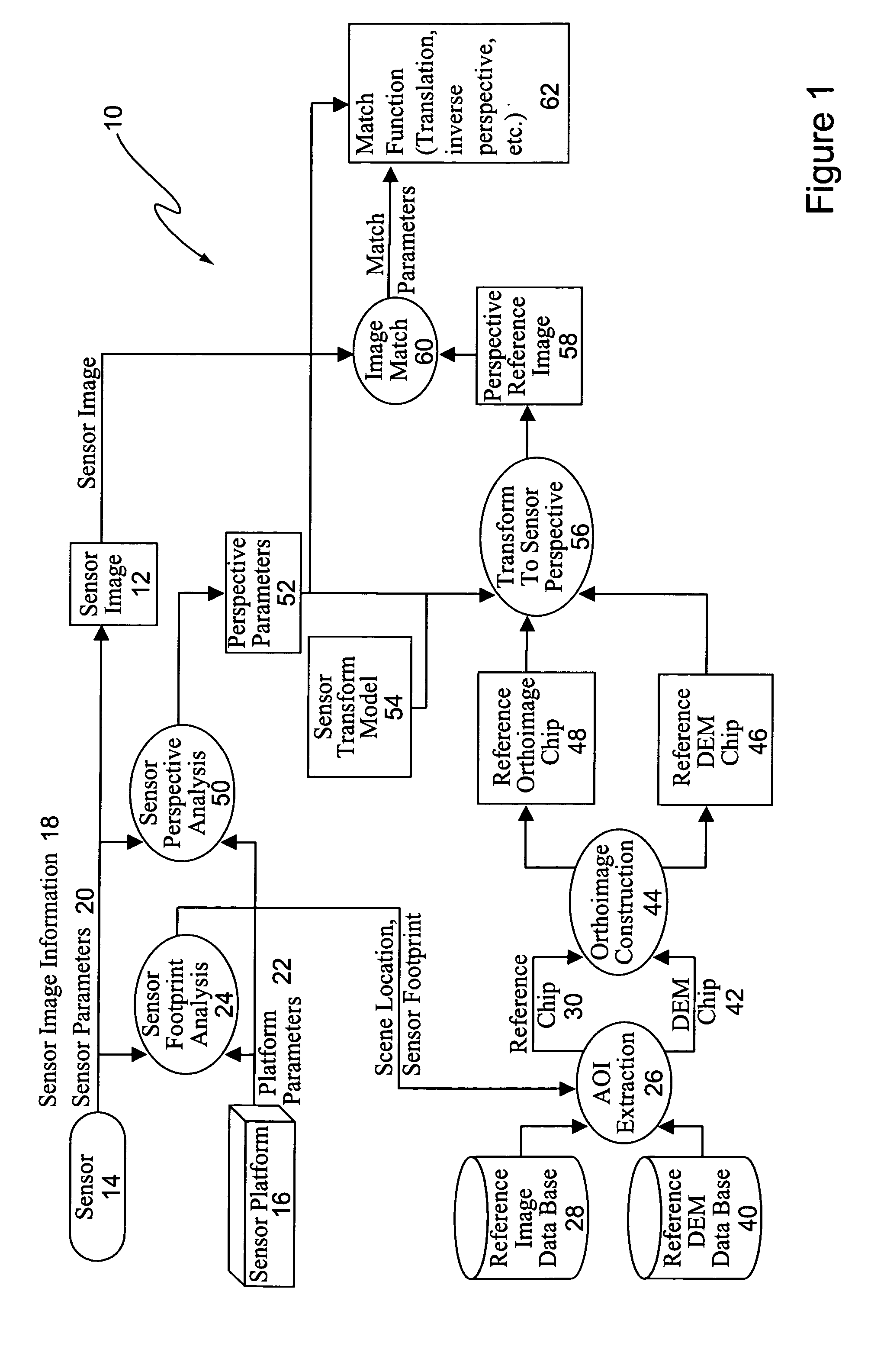
[0010] Generally, the present invention addresses the problem of relating sensor images to ground coordinate systems with high accuracy. This is accomplished by registering or aligning the sensor image with a precision geocoded reference image. Because of this high precision, the geocoding of the reference image can be transferred to the sensor image with accuracy comparable to that of the reference image. The geocoded reference image, such as a DPPDB image provided by the National Imagery and Mapping Agency, provides a known accuracy in relation to ground coordinates. The present invention also solves the problem of accurately registering a small sensor image to a much larger reference image, which may be taken as a stereo pair of images for some embodiments of this invention where the two images have significantly different perspectives of the scene.
[0011] One aspect of this invention makes use of knowledge of the approximate location of the scene as it is found in the reference image to limit the search area in attempting to match the small image to the larger image. Another aspect of the invention is the use of approximate knowledge of the sensor location and orientation, or the sensor model, at the time when the scene is imaged, as that knowledge, combined with knowledge of the scene location, may be used to reduce the search process. Yet another novel aspect is the use of the geometry of the scene area, as known or derivable for the reference image around the scene area, or as known or derivable for the sensor image, to modify one or both of the images to have a common geometry; that is, to eliminate perspective differences that arise from the two different views of the scene as imaged separately by the sensor and the reference.
[0017] The reference chip is then transformed (distorted or warped) to depict the same perspective as shown in the sensor image. An elevation or 3-D surface model of the scene area is used to ensure sufficient fidelity in the warped reference that an adequate match can be obtained. Factors such as scale difference and geometric distortions introduced by the sensing process can be taken into account to further improve the fidelity of the geometric match. Alternatively, the sensor image may be warped to match the perspective of the reference image. Again, a 3-D surface model of the scene is used to enhance the fidelity of the warp, as is information about geometric distortions peculiar to the reference image. As another alternative, both images may be warped to a common geometry, again using 3-D surface models of the scene and information about the sensor geometry and geometric distortions related to the reference image to enhance fidelity of the geometric match.
[0022] Of particular importance is the ability obtained using the invention to identify the specific location in the reference image of a target point appearing in the sensor image, when said target may not even be depicted in the reference image, such as when the reference image was recorded at a time before the target was at that location in the scene area. By means of the spatial coordinates associated with each pixel in the reference image, the spatial scene coordinates of the unreferenced target may be discovered. In addition, by showing the corresponding location of the target point as mapped to the reference image, an observer examining the sensor image and its selected target point, and the reference image and its corresponding mapped target point, can perform a judgment of the validity of the registration result, and of the target point placement in the reference image.
[0023] Another advantage obtained by relating pixel locations between images arises when the sensor and reference images have very different viewing perspectives of the scene. It then becomes possible to take advantage of the different information that is available in the multiple views with their different perspectives. For example, if the sensor image presented a more horizontal, oblique view of the scene, and the reference was an overhead view of the scene, then small pixel selection changes along the line of sight in the oblique view would translate into large pixel location changes in the reference view, indicating a low precision in the pixel mapping from sensor to reference image along the line of sight. However, by adjusting the selected pixel location in the overhead reference, a more precise selection may be obtained on the reference image than could be achieved by adjusting the location in the sensor image. Effectively, in this situation, small adjustments in the overhead reference can represent sub-pixel location changes in the oblique sensor image. This may be particularly important when the reference image is used to provide geocoded or model-based coordinates of the selected point for a high precision measurement in scene coordinates.

Problems solved by technology

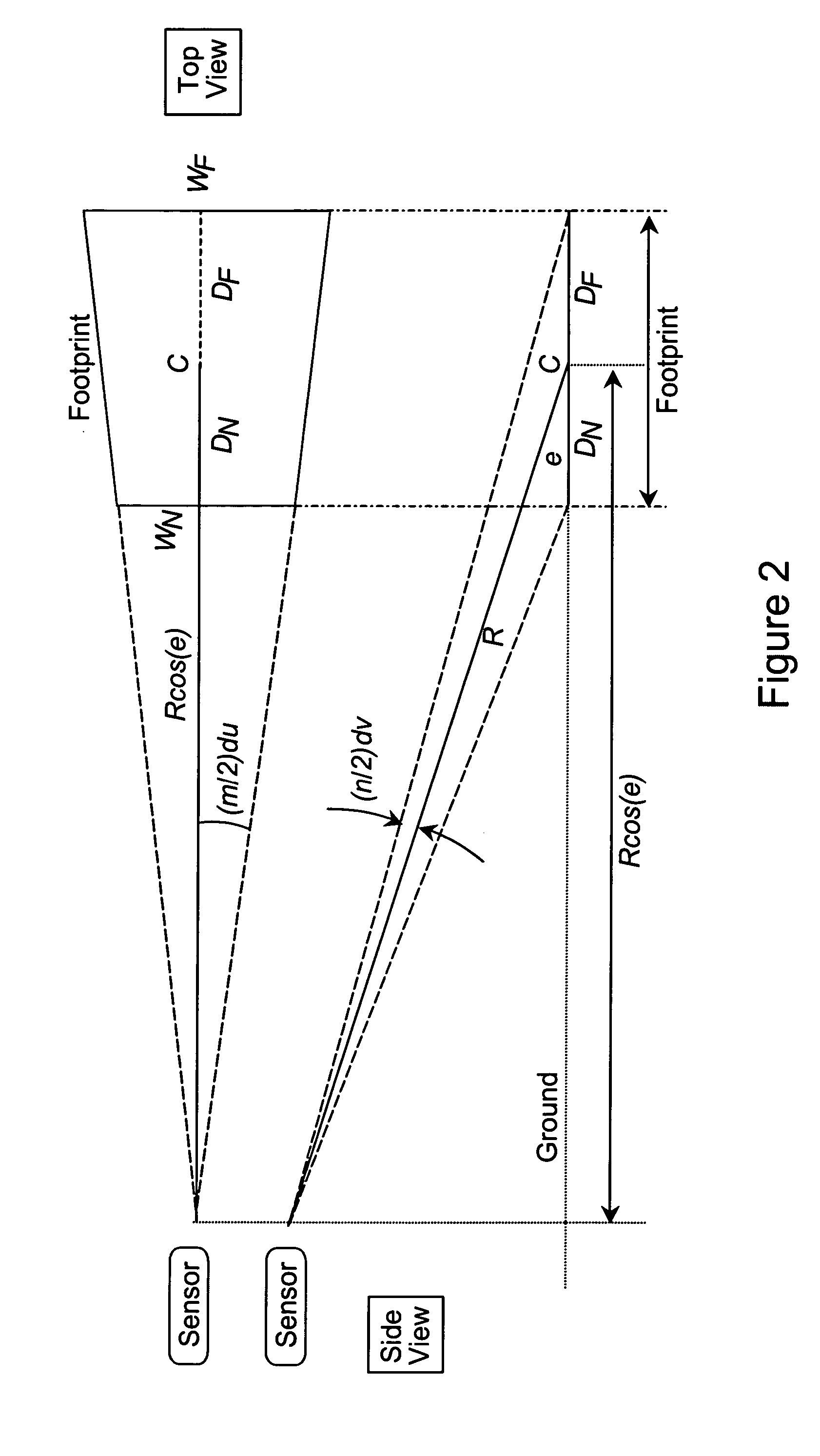
However, these measurements are actually estimates that involve uncertainties, producing uncertainty in where the sensed area or footprint actually is and in its actual orientation and size.

Method used


Image

  • Processing architecture for automatic image registration
  • Processing architecture for automatic image registration
  • Processing architecture for automatic image registration

Examples


Embodiment Construction

[0030] Generally, in accordance with the present invention, a small sensor image is matched to a larger reference image. The large reference image typically covers a relatively large area of the earth at a resolution of approximately the same, or better than, that normally expected to be seen in the sensor image. The reference area may be any area that can be the subject of a controlled imaging process that produces an image with known geometric characteristics and know geometric relationships between locations in the image and locations in the subject area. For example, the reference area may be a portion of a space assembly or an area on the human body. This reference typically involves hundreds of thousands, or even millions or more of pixels (picture elements) in each of its two dimensions, and may comprise a pair of such images in a stereoscopic configuration that admits stereography in viewing and measurement. The reference image is geocoded so that a geographic location can b...


PUM


Abstract

An image registration method and apparatus for automatically registering images of different perspectives, and where a sensor image is registered with a more precise reference image such that the geocoding of the reference image can be transferred to the sensor image.

Description

BACKGROUND OF THE INVENTION [0001] The present invention is directed to image registration, and more particularly to a system and method for automatically registering images of different perspectives and images from sensors with different internal geometry. [0002] Military fighter aircraft customers need a capability to target precision guided weapons. These include JDAM guided bombs as well as higher precision weapons that will eventually become available with target strike errors of 10 feet circular error at 50% probability (10 ft. CEP). [0003] Targeting sensors in fighter aircraft, such as forward-looking infrared (FLIR) or synthetic aperture radar (SAR), currently do not provide targeting of sufficient accuracy, even though the sensors provide images of the target area in which the pilot can precisely select a pixel location for the target. This is because sensor pointing controls of sufficient accuracy are not currently employed and are very expensive to implement, and there is...

Claims


Application Information

Patent Timeline
Patent Type & Authority Applications(United States)
IPC IPC(8): G01C11/00G06T7/00G06V20/13
CPCG01C11/00G06T7/0024G06K9/0063G06T7/30G06V20/13
Inventor OLDROYD, LAWRENCE A.
Owner THE BOEING CO
Learn More