Closed loop control of nip pressure in a fuser system

a closed loop control and fuser technology, applied in the field of fuser systems, can solve the problems of premature failure, large reduction of both dwell time, and nip width and nip uniformity in the fuser, and achieve the effects of large nip width, improved fusing quality on thick paper, and large nip width

Active Publication Date: 2005-10-06
XEROX CORP
View PDF24 Cites 20 Cited by
  • Summary
  • Abstract
  • Description
  • Claims
  • Application Information

AI Technical Summary

Benefits of technology

[0009] In addition to these failure modes, it is at times desired that the nip width and nip uniformity in a fuser be altered on demand. For instance, the fusing quality on thick paper is improved with large nip widths, and the fusing quality on thin papers is often improved with small nip widths. The fusing latitude in the presence of varied media and images, therefore, is improved if the nip width can be accurately set and controlled.

Problems solved by technology

Unfortunately, several internal and external factors can cause the fuser system to drift outside of the designated specifications.
This hardening causes large reductions in both dwell time and creep, which causes premature failure (e.g., smaller nip widths that lead to insufficient fixing of the toner image and / or poor image quality, as well as to poor stripping of the image receiving substrate).
In addition to these failure modes, it is at times desired that the nip width and nip uniformity in a fuser be altered on demand.
However, each of these ‘solutions’ has serious problems.
Using technicians to reset the nip requires an on site visit by a technician and down time of the device.
Initially setting the nip width high above specifications usually causes paper handling and stripping issues, especially with lightweight papers.
Maintaining nip width uniformity is as critical as maintaining the average nip width, as a nip width uniformity out of specification results in two major failure modes.
The first is that the axial variation of nip width and pressure results in axial variation of toner adhesion / fix and axial variation of toner gloss, which can cause the fuser to fail to meet print-quality requirements.
The second is that the axial nip uniformity also controls the fuser's paper handling and wrinkling performance, so variations in uniformity can cause the fuser to fail for wrinkling, mis-stripping, or other paper-handling reasons.

Method used


Image

  • Closed loop control of nip pressure in a fuser system
  • Closed loop control of nip pressure in a fuser system
  • Closed loop control of nip pressure in a fuser system

Examples


Embodiment Construction

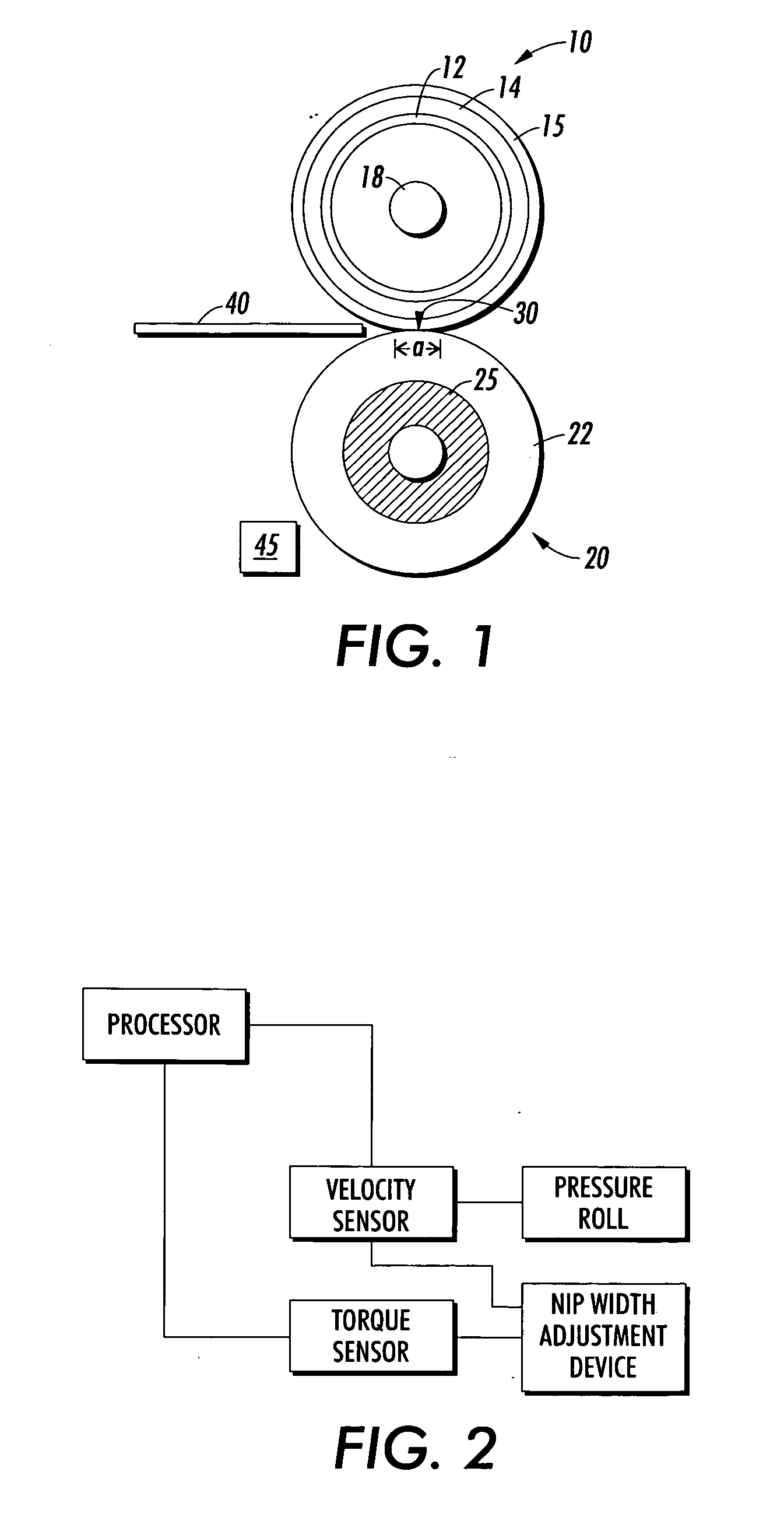
[0019] As was discussed above, a typical xerographic machine includes at least a toner image forming station, a transfer station to transfer the toner image to an image receiving substrate, and a fuser system to fix the toner image to the image receiving substrate. At the toner image forming station, a latent image of an original image is developed, typically on the surface of a photoconductor or photoreceptor, using a suitable toner material. The developed toner image is then transferred to an image receiving substrate such as paper, a transparency, etc., at a transfer station. Following transfer to the image receiving substrate, the toner image must then be fixed to the image receiving substrate, which is done by a fuser system that applies heat and pressure to the substrate having the toner image thereon.

[0020] A fuser system of the present invention is comprised of a fuser member that may be comprised of, for example, a fuser roll, or a fuser belt traveling around one or more (...


PUM


Abstract

A fuser system of a xerographic device, including a fuser member and a pressure member in which the pressure member is made to exert pressure upon the fuser member so as to form a nip having a nip width between the fuser member and the pressure member, wherein the nip width is set to within a specification nip width range, a drive system for driving said fuser member relative to said pressure roll; a sensor for monitoring the torque of said drive system; a processor in communication with the sensor that receives torque data from the sensor, wherein the processor determines a current nip pressure uniformity from the torque data and compares the current nip pressure uniformity to the specification nip pressure uniformity range, and a nip pressure adjustment device in communication with the processor, which adjusts the current nip pressure uniformity to be within the specification nip pressure uniformity range.

Description

CROSS-REFERENCE TO RELATED APPLICATIONS [0001] Reference is made to copending U.S. patent application Ser. No. XX / XXX,XXX (Attorney Docket No. D / A2573) entitled “Closed Loop Control Of NIP Width In A Fuser System”, filed on Dec. 19, 2003 by Donald M. Bott et al., is hereby incorporated by reference.BACKGROUND AND SUMMARY [0002] This invention relates to a fuser system that includes a closed loop control that controls a fuser's nip pressure. [0003] In the art of xerography or other similar image reproducing arts, a latent electrostatic image is formed on a charge-retentive surface, i.e., a photoconductor or photoreceptor. To form an image on the charge-retentive surface, the surface is first provided with a uniform charge after which it is exposed to a light or other appropriate image of an original document to be reproduced. The latent electrostatic image thus formed is subsequently rendered visible by applying any one of numerous toners specifically designed for this purpose. [0004...

Claims


Application Information

Patent Timeline
Patent Type & Authority Applications(United States)
IPC IPC(8): G03G15/20
CPCG03G15/2064
Inventor BOTT, DONALD M.ANTONIO, JOSEPH M.BURRY, AARON M.POLATKAN, OSMAN TODD
Owner XEROX CORP
Why Eureka
Try Eureka