

Conductive member, process cartridge, and electrophotographic apparatus
a technology of electrophotography and process cartridges, applied in the field of electrophotography apparatuses, can solve the problems of uneven distribution the gradual polarization of ion conducting agents in elastic layers, so as to achieve no charging sound and suppress the cost of power supply. low level
- Summary
- Abstract
- Description
- Claims
- Application Information
AI Technical Summary
Benefits of technology
Problems solved by technology
Method used
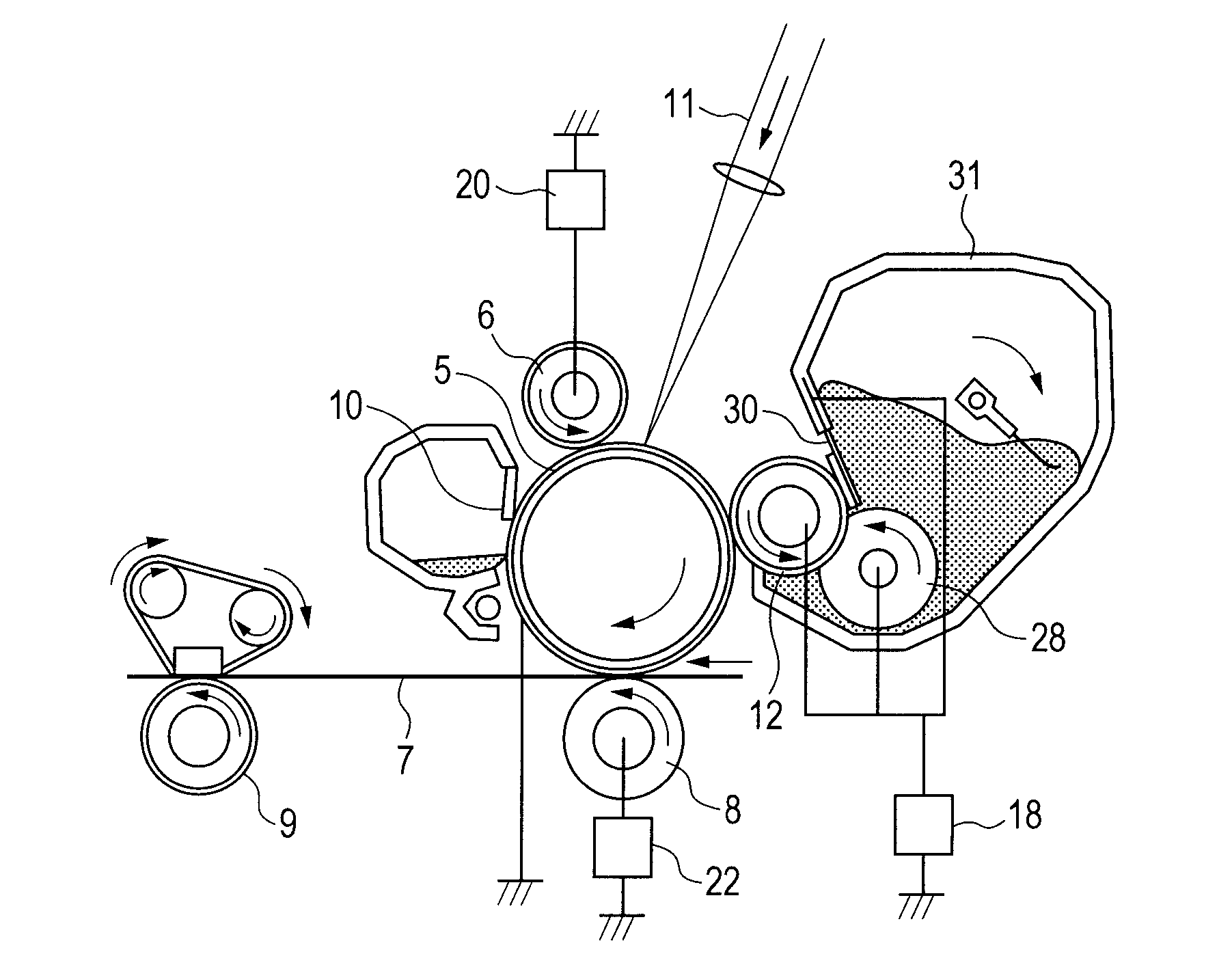
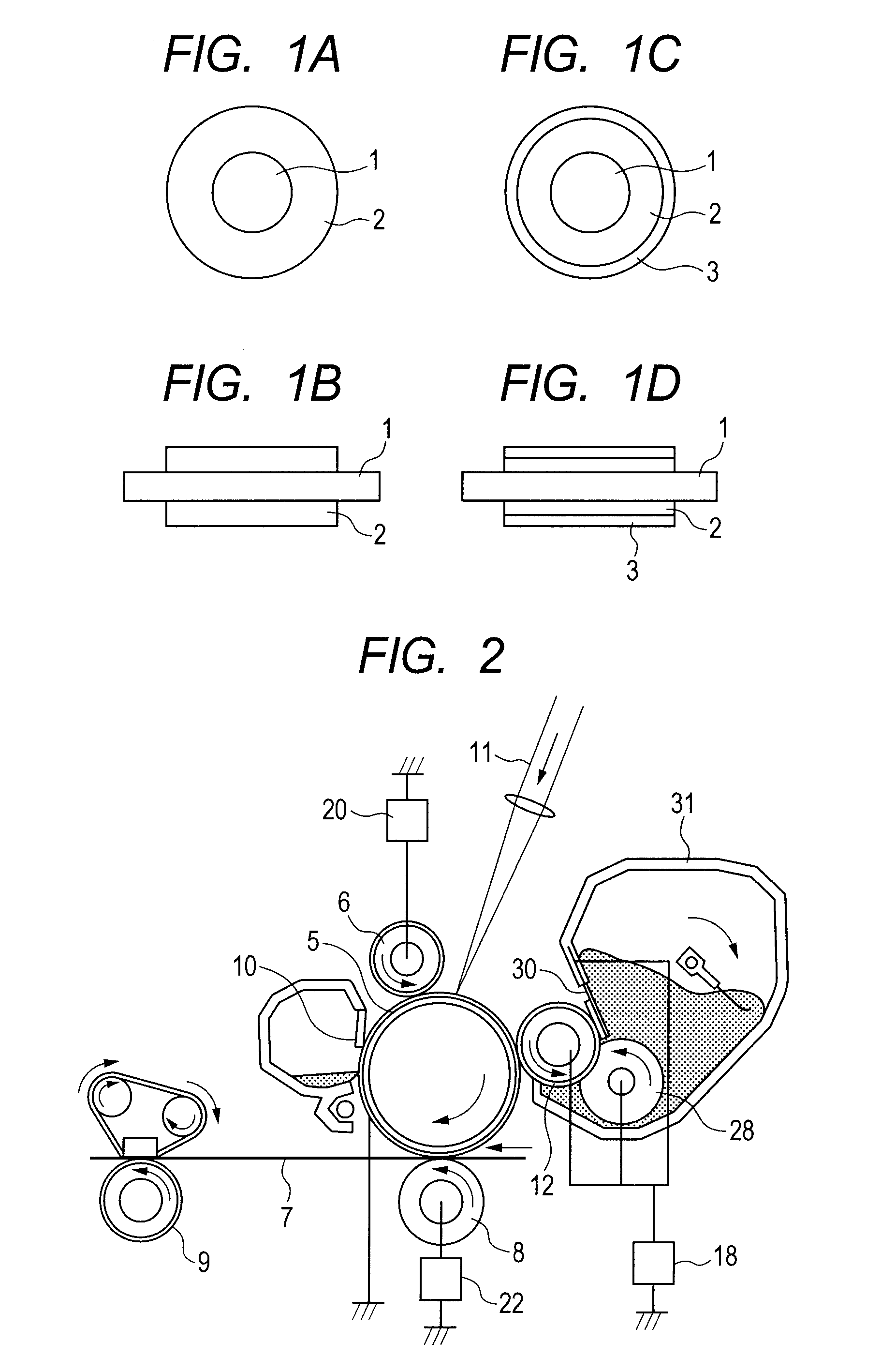
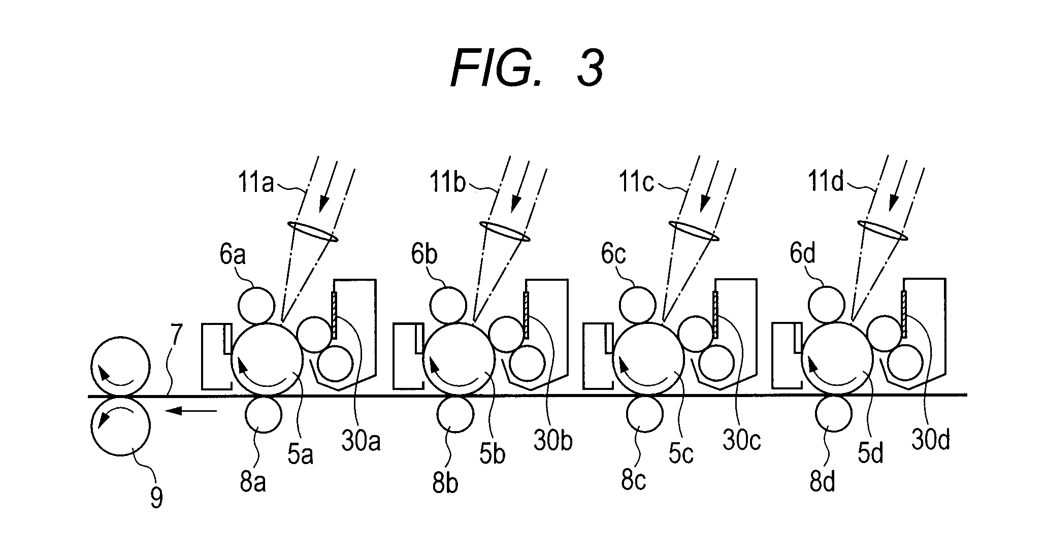
Image

Examples
example 1
[0099]100 Grams of the polymer No. 1 were dissolved in 4.0 L of dichloromethane and then the temperature of the solution was maintained at 40° C. in an argon atmosphere. 27.52 Grams of concentrated sulfuric acid were dropped to the dichloromethane solution. After the completion of the dropping, the temperature of the resultant liquid was increased to 80° C. and then the liquid was subjected to a reaction by being stirred for 72 hours while the liquid temperature was maintained at 80° C. Next, 1.0 L of methanol was dropped into the reaction solution to stop the reaction. The resultant reaction product was washed by repeating each of dissolution in toluene and reprecipitation with methanol three times. After that, the reaction product was dried in the air at a temperature of 80° C. for 24 hours. Next, the dried reaction product was dissolved in 1.0 L of toluene, and then the solution was subjected to dry distillation at a temperature of 120° C. while being stirred in a nitrogen atmosp...
example 2 to example 17
[0120]Thermoplastic elastomers Nos. 2 to 17 were each synthesized in the same manner as in Example 1 except that in Example 1, the polymer No. 1 was changed to a polymer with a polymer number shown in Table 5-1 and the blending quantity of concentrated sulfuric acid was changed to an amount shown in Table 5-1. The introduction ratio of a sulfonic group with respect to a double bond of a diene block was determined for each of the resultant thermoplastic elastomers Nos. 2 to 17 in the same manner as in Example 1 by employing proton NMR.
[0121]In addition, the states of the microphase-separated structures of the thermoplastic elastomers Nos. 2 to 17 were observed in the same manner as in Example 1. Table 5-2 shows the composition of each of the thermoplastic elastomers Nos. 1 to 17 each serving as the A-B-A type copolymer of the present invention, the kind of microphase-separated structure constituted of the polystyrene block of each elastomer, and the introduction ratio of a sulfonic g...
example 18
[0123]A sulfonic group was introduced to the polymer No. 1 in the same manner as in Example 1 except that the blending quantity of concentrated sulfuric acid in Example 1 was changed to 27.52 g. Next, 1.0 L of methanol was dropped into the reaction solution to stop the reaction. The resultant reaction product was washed by repeating each of dissolution in toluene and reprecipitation with methanol three times. After the washing, the reaction product was dried in the air at 80° C. for 24 hours. Next, the dried reaction product was dissolved in 1 L of toluene and then 200 g of glacial acetic acid were gradually dropped to the solution while the solution was stirred in a nitrogen atmosphere. After the completion of the dropping, the temperature of the resultant solution was increased and then the solution was stirred for 72 hours while its temperature was maintained at 80° C. The resultant reaction product was washed by repeating each of dissolution in toluene and reprecipitation with m...
PUM
| Property | Measurement | Unit |
|---|---|---|
| glass transition temperature | aaaaa | aaaaa |
| glass transition temperature | aaaaa | aaaaa |
| volume resistivity | aaaaa | aaaaa |
Abstract
Description
Claims
Application Information