Real-time visible light image and infrared image multi-channel fusion method and device

A technology of infrared image and fusion method, which is applied in the field of image processing, can solve the problems that the difference between the visible light image and the background area is not clear enough, the image texture of the infrared image is not detailed enough, and the influence (such as lighting and weather conditions, etc.) The effect of stable image quality and large amount of information

Active Publication Date: 2022-06-28
深圳鼎匠科技有限公司
View PDF7 Cites 3 Cited by
  • Summary
  • Abstract
  • Description
  • Claims
  • Application Information

AI Technical Summary

Problems solved by technology

[0002] In the field of image analysis, visible light images have a large amount of information and high pixel intensity, which can provide more intuitive details for computer vision tasks, but the image quality of visible light images is easily affected by the data collection environment (such as lighting and weather conditions). As a result, the difference between the main content (such as people) that needs to be highlighted and the background area in the visible light image is not clear enough; while the infrared image generated based on infrared thermal imaging technology can significantly distinguish the main content and the background area in the infrared image according to the difference in thermal radiation on the surface of the object The background area, but because the infrared image is usually a grayscale image that is difficult for the human eye to distinguish, and the contrast of the infrared image is low and the image is blurred, the image texture of the infrared image is not detailed enough

Method used


Image

  • Real-time visible light image and infrared image multi-channel fusion method and device
  • Real-time visible light image and infrared image multi-channel fusion method and device
  • Real-time visible light image and infrared image multi-channel fusion method and device

Examples


Embodiment 1

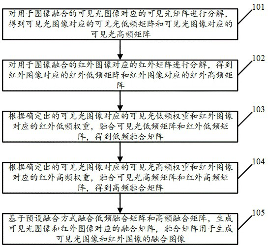
[0107] see figure 1 , figure 1 It is a schematic flowchart of a real-time visible light image and infrared image multi-channel fusion method disclosed in the embodiment of the present invention. in, figure 1 The described real-time visible light image and infrared image multi-channel fusion method can be applied to the fusion process of visible light image and infrared image, including the fusion process of visible light image and infrared image collected at the same time and in the same field of view in real time, such as infrared image. The real-time fusion process of the detection video and the visible light detection video is not limited in the embodiment of the present invention. like figure 1 As shown, the real-time visible light image and infrared image multi-channel fusion method may include the following operations:

[0108] 101. Decompose a visible light matrix corresponding to a visible light image used for image fusion to obtain a visible light low frequency ma...

Embodiment 2

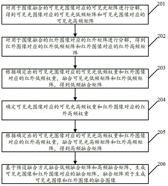
[0198] see figure 2 , figure 2 It is a schematic flowchart of another real-time visible light image and infrared image multi-channel fusion method disclosed in the embodiment of the present invention. in, figure 2 The described real-time visible light image and infrared image multi-channel fusion method can be applied to the fusion process of visible light image and infrared image, including the fusion process of visible light image and infrared image collected at the same time and in the same field of view in real time, such as infrared image. The real-time fusion process of the detection video and the visible light detection video is not limited in the embodiment of the present invention. like figure 2 As shown, the real-time visible light image and infrared image multi-channel fusion method may include the following operations:

[0199] 201. Decompose a visible light matrix corresponding to a visible light image used for image fusion to obtain a visible light low fr...

Embodiment 3

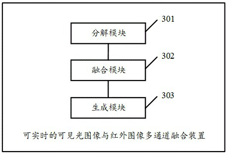
[0239] see image 3 , image 3 It is a schematic structural diagram of a real-time visible light image and infrared image multi-channel fusion device disclosed in the embodiment of the present invention. in, image 3 The described real-time visible light image and infrared image multi-channel fusion device can be applied to the fusion process of visible light image and infrared image, including the fusion process of visible light image and infrared image collected in real time at the same time and in the same field of view, such as infrared image. The real-time fusion process of the detection video and the visible light detection video is not limited in the embodiment of the present invention. like image 3 As shown, the real-time visible light image and infrared image multi-channel fusion device may include:

[0240] The decomposition module 301 is configured to decompose the visible light matrix corresponding to the visible light image used for image fusion, obtain the v...


PUM


Abstract

The invention discloses a real-time visible light image and infrared image multi-channel fusion method and device, and the method comprises the steps: decomposing a visible light matrix corresponding to a visible light image to obtain a visible light low-frequency matrix and a visible light high-frequency matrix, and decomposing an infrared matrix corresponding to an infrared image to obtain a visible light low-frequency matrix and a visible light high-frequency matrix; obtaining an infrared low-frequency matrix and an infrared high-frequency matrix; according to the visible light low-frequency weight and the infrared low-frequency weight, fusing the visible light low-frequency matrix and the infrared low-frequency matrix to obtain a low-frequency fusion matrix, and according to the visible light high-frequency weight and the infrared high-frequency weight, fusing the visible light high-frequency matrix and the infrared high-frequency matrix to obtain a high-frequency fusion matrix; and fusing the low-frequency fusion matrix and the high-frequency fusion matrix based on a preset fusion mode to generate a fusion matrix corresponding to the visible light image and the infrared image. Visibly, the visible light image and the infrared image can be fused by implementing the method, so that the resolution of the main body content and the background area in the image is improved, and meanwhile, the meticulous degree of the image texture is improved.

Description

technical field [0001] The invention relates to the technical field of image processing, in particular to a real-time visible light image and infrared image multi-channel fusion method and device. Background technique [0002] In the field of image analysis, visible light images have a large amount of information and high pixel intensity, which can provide more intuitive details for computer vision tasks, but the image quality of visible light images is easily affected by the data collection environment (such as lighting and weather conditions), As a result, the difference between the main content (such as people) that needs to be highlighted in the visible light image and the background area is not clear enough; while the infrared image generated based on infrared thermal imaging technology can significantly distinguish the main content in the infrared image from the thermal radiation difference on the surface of the object. However, since the infrared image is usually a gr...

Claims


Application Information

Patent Timeline
Patent Type & Authority Applications(China)
IPC IPC(8): G06T5/50G06T5/20
CPCG06T5/50G06T5/20G06T2207/10048G06T2207/10024G06T2207/20221G06T2207/20032
Inventor 周振彬娄珂宾朝林秦文礼
Owner 深圳鼎匠科技有限公司
Why Eureka
Try Eureka