
Modular wide-range transceiver

a wide-range, module technology, applied in the field of communication systems, can solve the problems of large space in the rf unit, unfavorable use of filter banks, and difficult integration of all these systems, and achieve the effect of efficiently and economically calibrating the modules and ensuring the effect of placemen

Active Publication Date: 2005-10-06
HARRIS STRATEX NETWORKS
View PDF4 Cites 40 Cited by
  • Summary
  • Abstract
  • Description
  • Claims
  • Application Information

AI Technical Summary

Benefits of technology

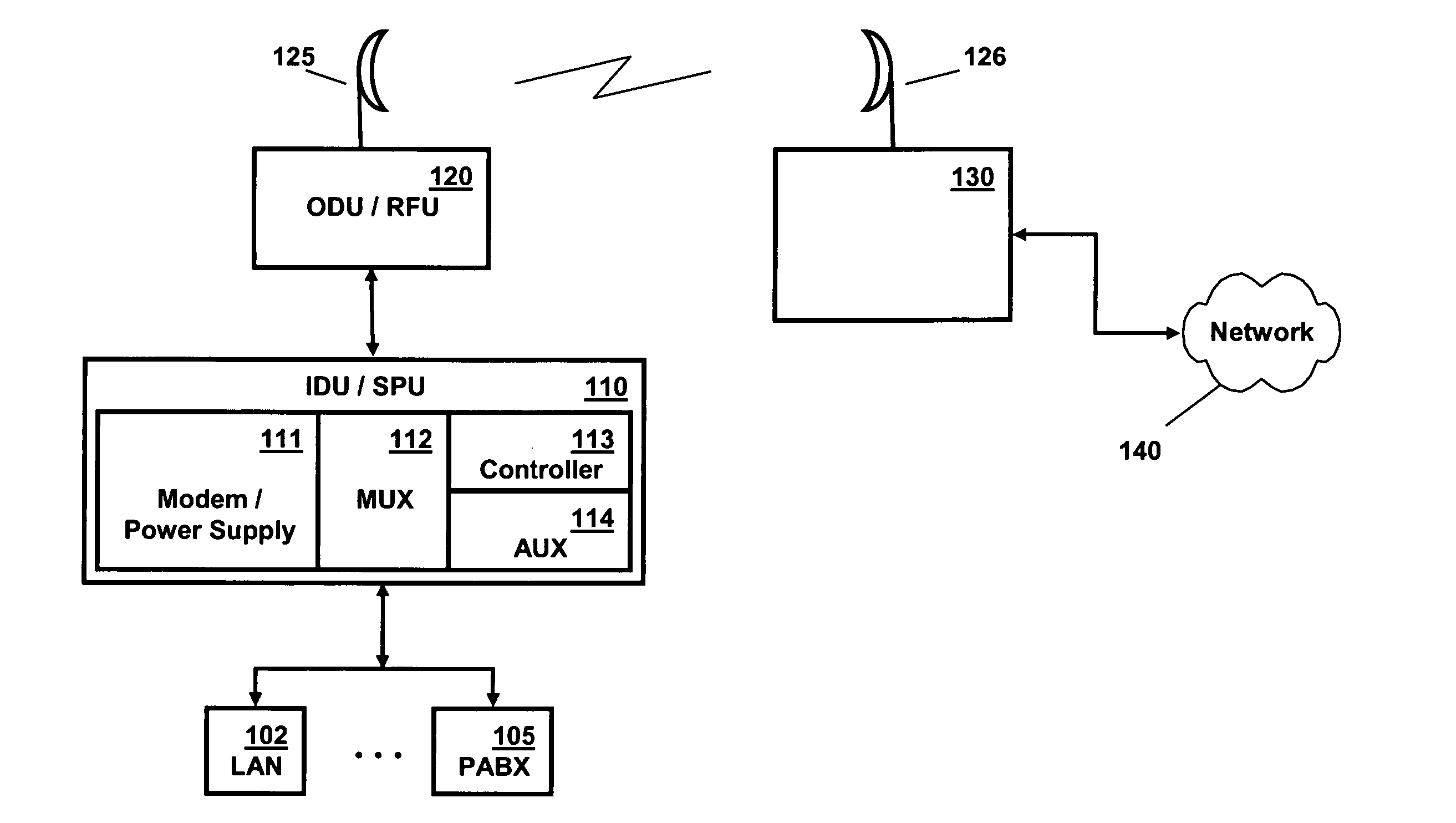
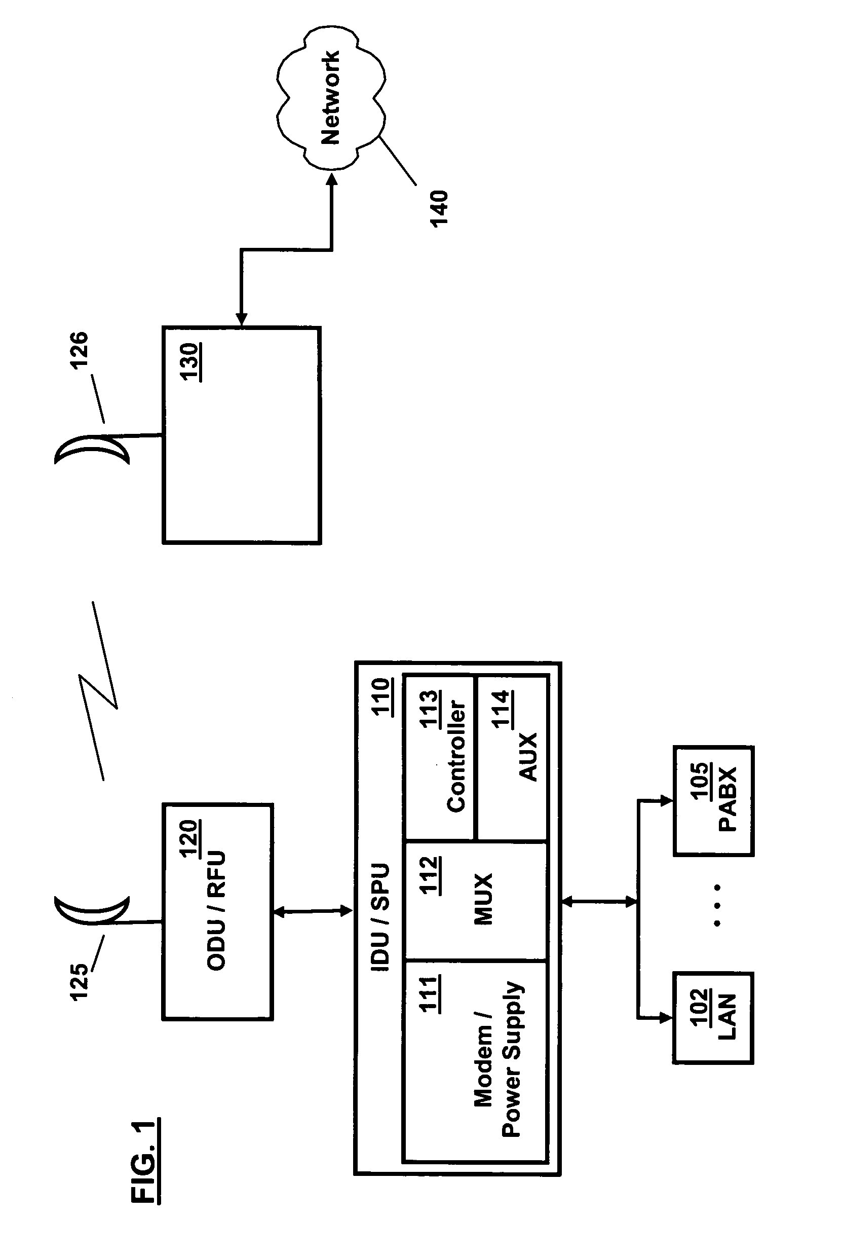
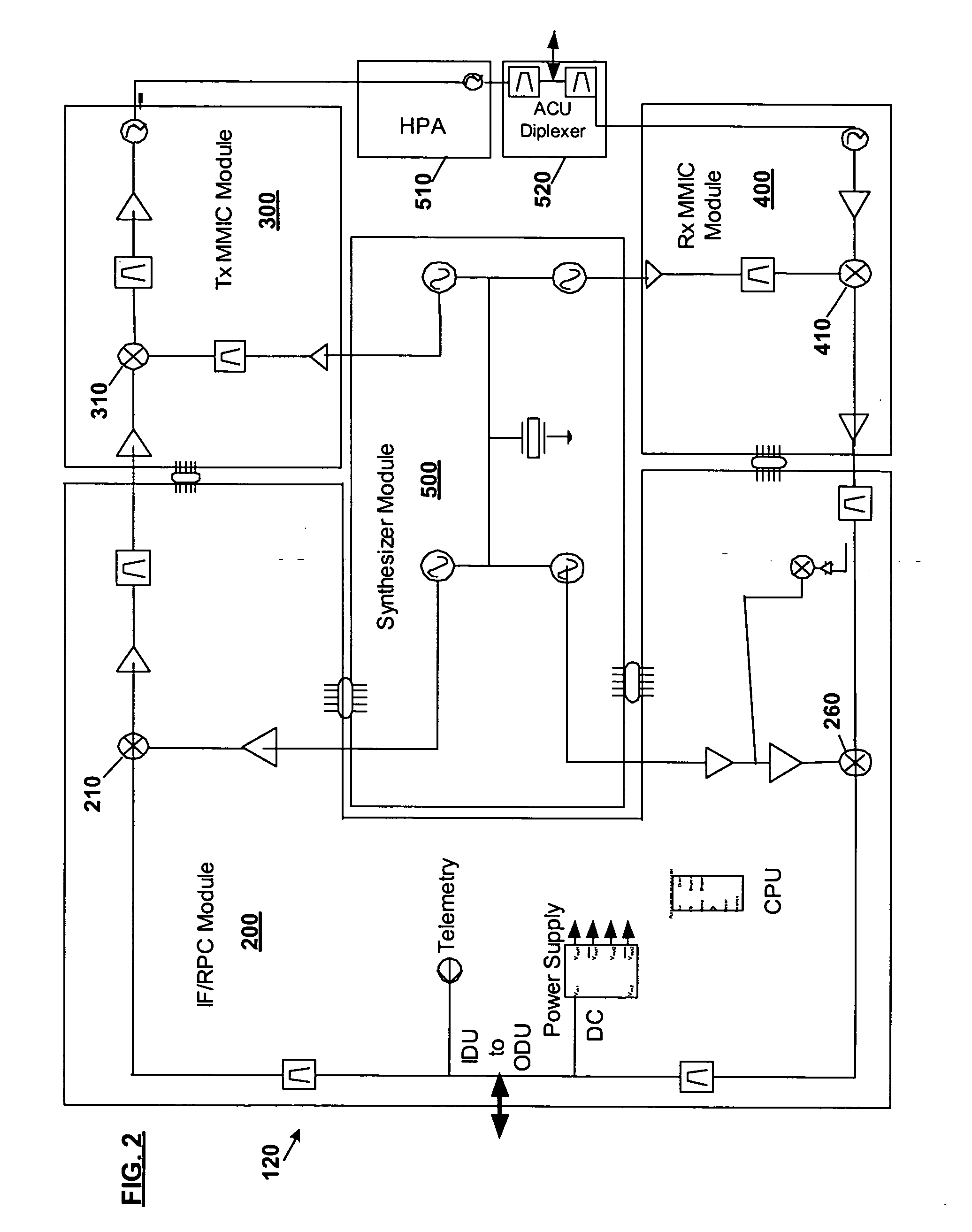
[0008] The present invention provides a method, apparatus, and processor instructions for wide-range microwave communications. In an exemplary embodiment, a wide-range transceiver has pre-calibrated modular units including an IF radio processing card, an RF transmitter module, and an RF receiver module. Calibration factors are loaded into a memory (e.g., EEPROM) in each module during production. Certain additional calibration factors may also be loaded upon installation and use, such as a one time calibration for the type and length of cable connecting the RF unit to a remote SPU (signal processing unit). A processor in the RF unit is responsive to control signaling indicating a desired transmitter or receiver configuration (e.g., a particular frequency, bandwidth and modulation), to attenuate the signal in the transmitter / receiver path based on the predetermined calibration factors from the applicable modules. If changes are needed for new transceiver configurations that cannot be accommodated by software changes alone, new modules can be readily inserted without requiring an expensive swap-out of the RF unit. A method for efficiently and economically calibrating the modules is also disclosed.

Problems solved by technology

Making all these systems work together has become a daunting challenge.
However, such filter banks, for use across many different bandwidths, are not cost effective.
They also occupy significant space in the RF unit, which defeats a key objective of keeping the RF unit small and compact.
A different kind of problem exists when with trying to implement the transmitter path in a wide-range microwave transceiver.
These typically require the RF unit to be calibrated as a whole unit, leading to complexity in the overall test setup, increased costs, and increased test times.
In both cases, current designs fail to adequately address the problem created by the needs of service providers to more frequently change their network configurations.

Method used


Image

  • Modular wide-range transceiver
  • Modular wide-range transceiver
  • Modular wide-range transceiver

Examples


Embodiment Construction

[0019] The limitations of prior systems described above are overcome by the novel improvements of our invention, which are illustrated by the following detailed description of a preferred embodiment. In this embodiment, common transmit path and receive path designs are implemented in modular form. Despite the common designs, by using a modulation index and combining modulation / capacity correction factors, a variety of modulations (e.g., QPSK, 256QAM), capacities (e.g., 2T1, STM1), and bandwidths may be transceived without resort to redundant or expensive circuitry. This improvement also allows for a per-module room-temperature calibration process, performed during standard module production, which substantially reduces per unit production costs and factory capital costs for testing. Moreover, by appropriate location of attenuators, detectors, and filters, together with software control and correction mechanisms, the embodiment disclosed can achieve sustained performance across a ver...


PUM


Abstract

The present invention provides a method, apparatus, and processor instructions for wide-range microwave communications. In an exemplary embodiment, a wide-range transceiver is made having pre-calibrated modular units including an IF radio processing card, an RF transmitter module, and an RF receiver module. Calibration factors are loaded into a memory (e.g., EEPROM) in each module during production. Certain additional calibration factors may also be loaded upon installation, such as a one time calibration for the type and length of cable connecting the RF unit to a remote SPU (signal processing unit). A processor in the RF unit is responsive to control signaling indicating a desired transmitter or receiver configuration (e.g., a particular frequency, bandwidth and modulation), to attenuate the signal in the transmitter / receiver path based on the predetermined calibration factors from the applicable modules. A method for calibrating the modules is also disclosed.

Description

TECHNICAL FIELD [0001] Our invention generally relates to communications systems and, more specifically, the invention is related to the field of microwave wireless transceivers. BACKGROUND OF THE INVENTION [0002] Mankind has an insatiable desire to communicate. This demand has spurred on the development of a great variety of communications technologies—both wired, in the form of telecommunications and data networks, and wireless, such as cellular, microwave and satellite systems. [0003] Making all these systems work together has become a daunting challenge. Back when there was only one dominant service provider—the Bell System in the U.S. and Canada—it was relatively straightforward to add a new technology to a fairly uniform network. In the case of wireless systems, the upgrades often involved a complete swap-out of the existing RF (radio frequency) units. But, the limited number of units, by today's measures, and fixed transceiver characteristics (e.g., a single modulation type),...

Claims


Application Information

Patent Timeline
Patent Type & Authority Applications(United States)
IPC IPC(8): H04B7/00H04B17/00
CPCH04B17/13H04B17/21H04B17/309
Inventor SHEN, YINGTHEBERGE, GUYJAO, SANCONCILIO, FABIOTRUMP, SHAUEN THOMASPECK, DON E.
Owner HARRIS STRATEX NETWORKS
Learn More