Lock-up control for torque converter

a technology of torque converter and control device, which is applied in fluid gearings, instruments, gearings, etc., can solve the problems of affecting the operation of the vehicle, and the transmission ratio cannot be changed to a lower gear side, so as to prevent the occurrence of muffled sound and noise, and increase the vehicle speed

Active Publication Date: 2005-10-06
JATCO LTD
View PDF2 Cites 30 Cited by
  • Summary
  • Abstract
  • Description
  • Claims
  • Application Information

AI Technical Summary

Benefits of technology

[0005] An object of this invention is to secure an increase of the vehicle speed when the torque co...

Problems solved by technology

However, when there is not enough torque at a time of starting the vehicle on an ascending slope, the vehicle is started at a transmission ratio (or gear ratio) on the lowest gear side, thus the...

Method used


Image

  • Lock-up control for torque converter
  • Lock-up control for torque converter
  • Lock-up control for torque converter

Examples


Embodiment Construction

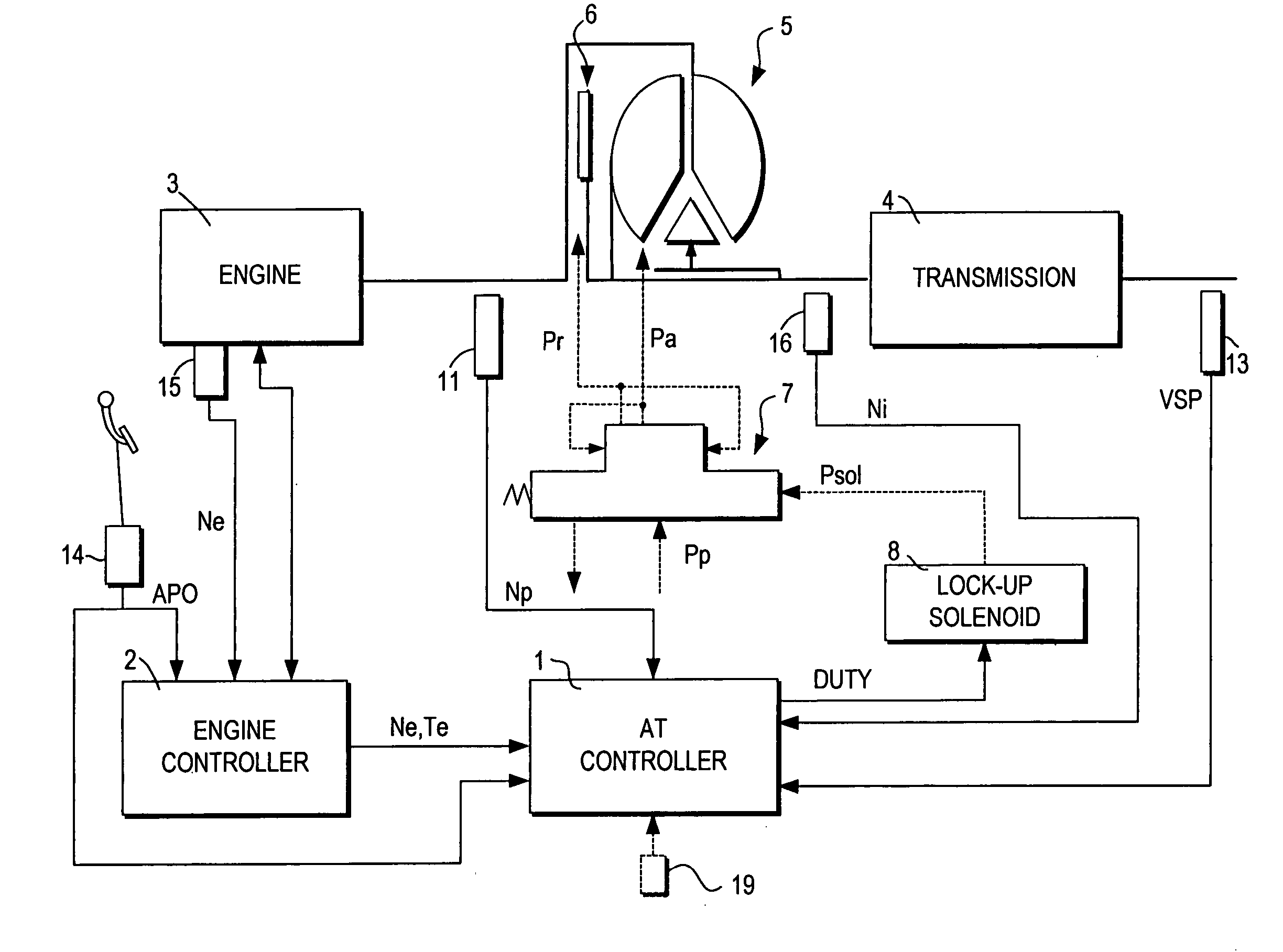
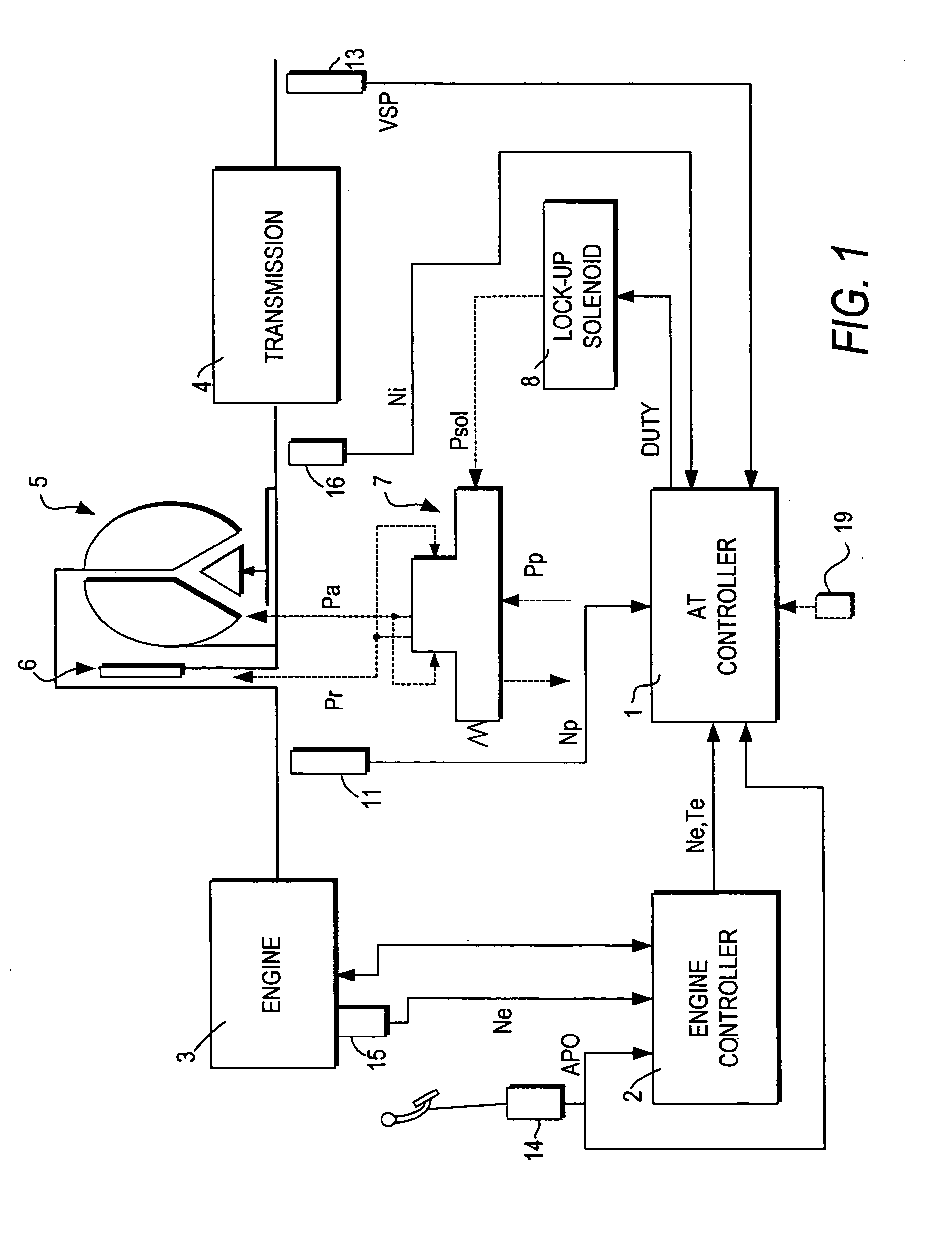
[0014]FIG. 1 shows a vehicle in which is mounted an automatic transmission according to this embodiment. An engine 3 is coupled to an automatic transmission comprising a transmission 4 and a torque converter 5. The transmission 4 may comprise one or more planetary gear sets, or a continuously variable transmission (CVT). The torque converter 5 comprises a lock-up clutch 6. The lock-up clutch 6 is selectively brought to a lock-up state (engaged state) or an unlock-up state (disengaged state) in accordance with the operational status of the vehicle.

[0015] The torque converter 5 has incorporated therein the lock-up clutch 6 which is rotated along with a torque converter output element (turbine). When the lock-up clutch 6 is locked to a torque converter input element (impeller), the torque converter 5 is brought to the lock-up state where the input and output elements are directly coupled to each other.

[0016] The lock-up clutch 6 is operated in accordance with a differential pressure ...


PUM


Abstract

A lock-up clutch control device controls a lock-up clutch (6) provided in a torque converter (5) which is mounted between the engine (3) and transmission (4) provided in a vehicle. The lock-up clutch control device switches the state of the torque converter (5) between a converter state and a lock-up state by controlling a differential pressure supplied to the lock-up clutch. The lock-up clutch control device includes a sensor (13, 19) for detecting a rise of a vehicle speed; a differential pressure generator (7, 8) which generates the differential pressure supplied to the lock-up clutch; and a controller (1). The controller is programmed to command the differential pressure generator (7, 8) to lock the lock-up clutch (6) when the vehicle speed exceeds a predetermined low vehicle speed (V1), after the vehicle is started; subsequently monitor the rise of the vehicle speed; and command the differential pressure generator (7, 8) to unlock the lock-up clutch when the monitored rise of the vehicle speed is lower than a preset value (Vss/αs).

Description

FIELD OF THE INVENTION [0001] This invention relates to a control device for controlling lock-up of a torque converter. BACKGROUND OF THE INVENTION [0002] In a torque converter comprising a lock-up clutch, control of a differential pressure at the front and rear of the lock-up clutch (lock-up differential pressure) locks / disengages the lock-up clutch. The lock-up differential pressure is gradually raised from a predetermined initial differential pressure in order to shift the torque converter from a converter state to a lock-up state. The torque converter is shifted from the converter state to the lock-up state through a slip state. The lock-up clutch is released or disengaged in the converter state, slips in the slip state, and is locked in the lock-up state. [0003] Japanese Patent Application Laid-Open No. 2002-205576 published by the Japanese Patent Office in 2002 discloses control of a lock-up clutch which improves fuel economy by performing locking up from a low vehicle speed. ...

Claims


Application Information

Patent Timeline
IPC IPC(8): F16H61/14F16H59/44F16H59/48G06F7/00
CPCF16H59/44F16H59/48F16H61/143F16H2059/405F16H2057/0012
Inventor IMAMURA, TATSUYASEKIYA, HIROSHIIIDA, TOSHIJIDOHI, KOJI
Owner JATCO LTD
Why Eureka
Try Eureka