Communication method and processor

Inactive Publication Date: 2005-10-06
LAPIS SEMICON CO LTD
View PDF5 Cites 7 Cited by
  • Summary
  • Abstract
  • Description
  • Claims
  • Application Information

AI Technical Summary

Benefits of technology

[0007] An object of the present invention is to provide a method of communication between a processor and an external device in which the processor's CPU does not have to set configuration data such as data specifying the communication speed both in the processor's data communication interface and in the external device.
[0012] According to the invention, the CPU processing load occasioned by communication with the external device is reduced because the CPU has to set the communication parameter in only one place.

Problems solved by technology

Both settings are conventionally carried out by the processor's CPU, but this places an undesirable burden on the CPU, particularly when the configuration data have to be set frequently.

Method used


Image

  • Communication method and processor
  • Communication method and processor
  • Communication method and processor

Examples


second embodiment

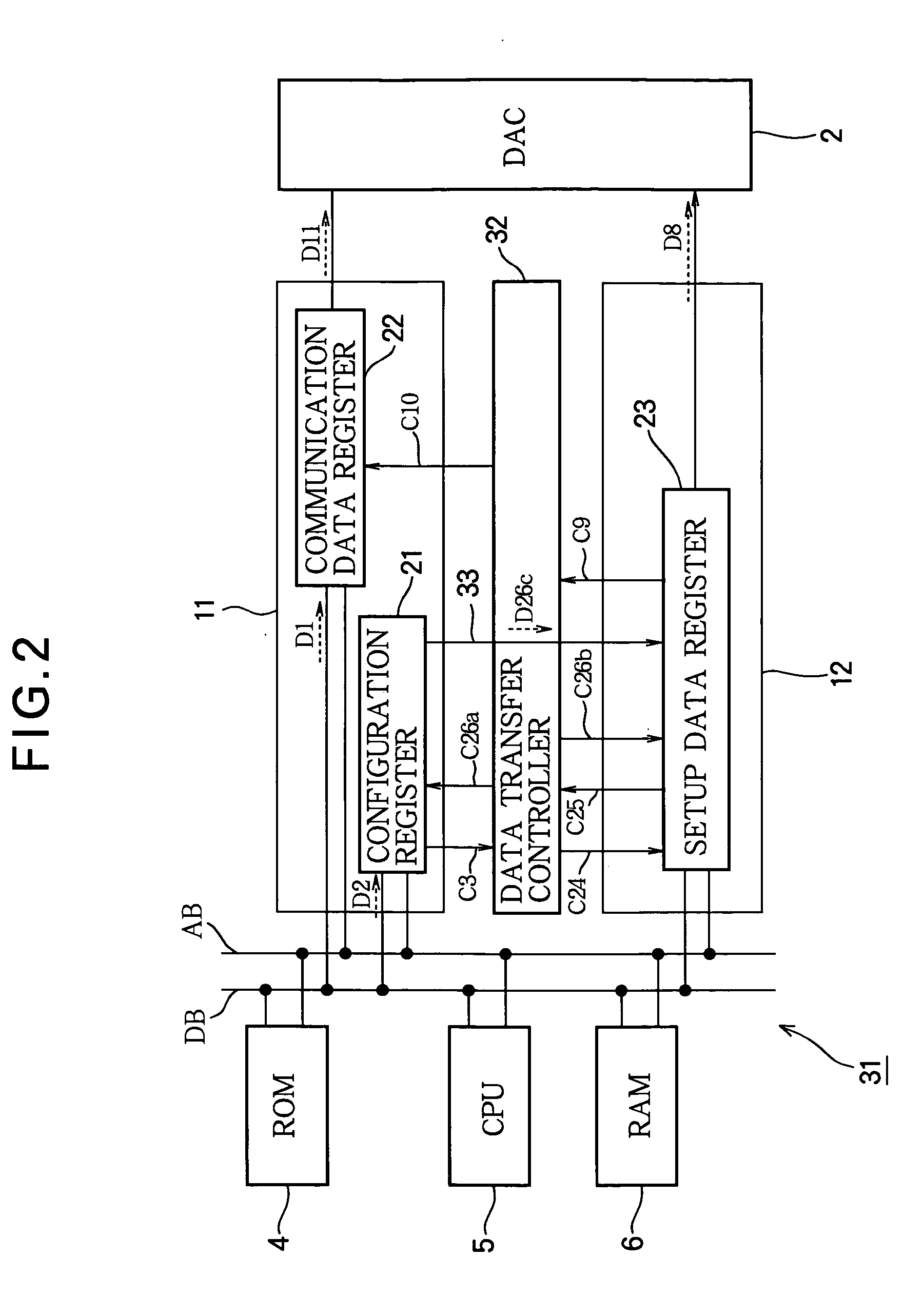
[0046] A second embodiment of the invention will be described with reference to FIG. 2.

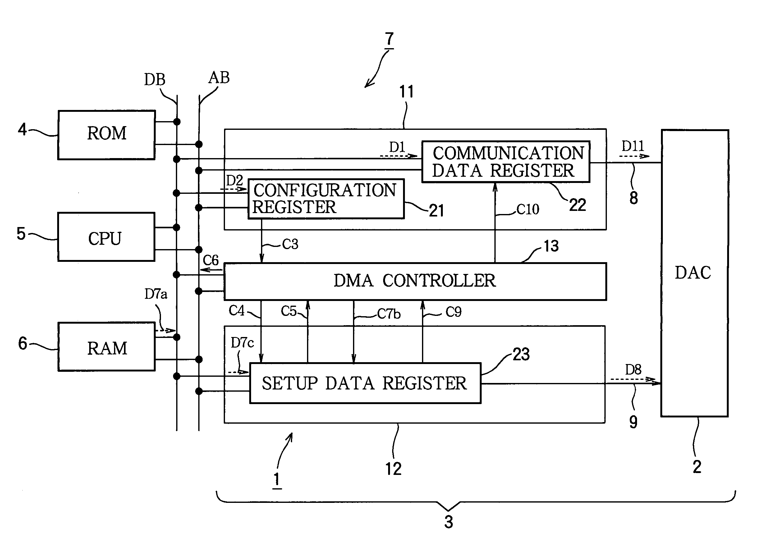
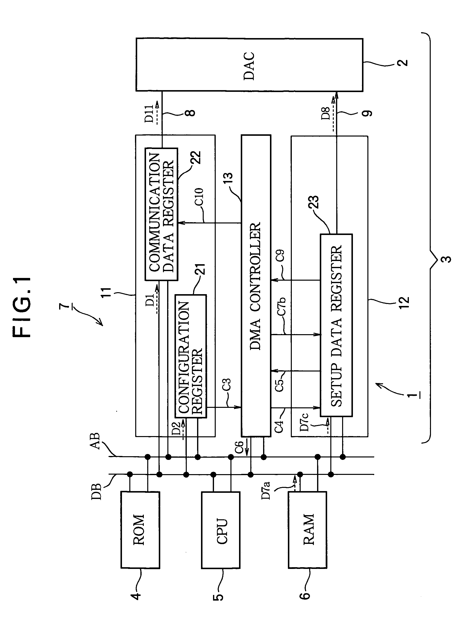
[0047] The processor 31 in the second embodiment differs from the processor in the first embodiment by replacing the DMA controller with a data transfer controller 32, and including a dedicated data bus 33. Whereas the DMA controller in the first embodiment transferred configuration data from the RAM 6 into the setup data register 23 in the communication setup interface 12, the data transfer controller 32 in the second embodiment transfers configuration data from the configuration register 21 in the data communication interface 11 to the setup data register 23 in the communication setup interface 12, using the dedicated data bus 33.

[0048] A description of the operation of a digital audio player will be given below, focusing on the procedure for setting configuration data. This procedure can be divided into ten steps, numbered S21 to S30 below. The configuration data are denoted D2, D26c, and D8 ...

third embodiment

[0061] A third embodiment of the invention will be described with reference to FIG. 3.

[0062] The processor 41 in the third embodiment differs from the processor 31 in the second embodiment in FIG. 2 by inserting a decoder 34 on the dedicated data bus 33 between the configuration register 21 and the setup data register 23. In the third embodiment, when configuration data are transferred from the configuration register 21 to the setup data register 23, the decoder 34 reformats the transferred configuration data.

[0063] When the configuration data format used in the data communication interface 11 differs from the format used in the digital-to-analog converter 2, the decoder 34 receives the configuration data, converts the format of the received configuration data from the format suitable for the configuration register 21 in the data communication interface 11 to the format suitable for being set in the digital-to-analog converter 2, and transfers the reformatted configuration data.

[...

fourth embodiment

[0065] A fourth embodiment of the invention will be described with reference to FIG. 4.

[0066] The processor 41 in the fourth embodiment differs from the processor 41 in the third embodiment by replacing the communication setup interface 12 and the digital-to-analog converter 2 with an output port controller 42 and a digital-to-analog converter 43 that does not include a register for storing configuration data. The digital-to-analog converter 43 operates according to control signals applied to a control input terminal 43c.

[0067] Whereas, in the third embodiment, configuration data to be set in the digital-to-analog converter 2 are written in the setup data register 23 in the communication setup interface 12, and the setup data register 23 transmits the configuration data to the digital-to-analog converter 2, in the fourth embodiment, configuration data, such as data specifying the data communication speed, are written in a control data register 44 in the output port controller 42, ...


PUM


Abstract

A processor has a central processing unit and a first interface. The central processing unit sets a communication parameter in a configuration register in the communication interface. A direct memory access controller or a data transfer controller then sets the same parameter in a register in a communication setup interface or an output port controller, which transmits the parameter to an external device with which the processor communicates through the communication interface. Alternately, the central processing unit sets the communication parameter in the communication setup interface or output port controller, and the direct memory access controller or data transfer controller sets the same parameters in the configuration register in the communication interface. Either scheme reduces the load on the central processing unit.

Description

BACKGROUND OF THE INVENTION [0001] 1. Field of the Invention [0002] The present invention relates to a method of communication between a processor and an external device, and to a processor employing this method of communication. [0003] 2. Description of the Related Art [0004] Japanese Unexamined Patent Application Publication No. 5-336296 discloses a communication method in which the functions of a communication terminal such as a facsimile machine are set up according to values sent through an interface that connects the terminal to a host computer. [0005] Japanese Unexamined Patent Application Publication No. 6-46103 discloses a communication method in which, upon reception of data according to a predetermined protocol, a central processing unit (CPU) sends a direct memory access (DMA) request signal to a DMA controller, which then transfers data between a memory device and a communication device without CPU intervention. [0006] In conventional communication methods such as these...

Claims


Application Information

Patent Timeline
IPC IPC(8): G06F13/12G06F13/28
CPCG06F13/28
Inventor TODA, KENTARO
Owner LAPIS SEMICON CO LTD
Why Eureka
Try Eureka