Command multiplex number monitoring control scheme and computer system using the command multiplex number monitoring control scheme

Active Publication Date: 2005-10-06
GOOGLE LLC
View PDF6 Cites 12 Cited by
  • Summary
  • Abstract
  • Description
  • Claims
  • Application Information

AI Technical Summary

Benefits of technology

[0007] An object of the present invention is to provide a command multiplex number monitoring control scheme capable of avoiding issue of the QF status and getting rid of system performance degradation without adding command processing resources, and a computer system using this command multiplex number monitoring control scheme.
[0014] According to the present invention, the following advantages are obtained.
[0015] (1) Connections to higher rank apparatuses exceeding the command processing multiplex limit number in the storage apparatus can be prevented.
[0018] (4) When the storage apparatus is connected to a higher rank apparatus that does not stop command multiplex issue even if the higher rank apparatus has received a QF status, it becomes possible to provide priority for each world wide name WWN—logical unit LU. When setting access permissions that are not used at the same time, command processing resources can be utilized efficiently.

Problems solved by technology

Upon receiving the QF status, the higher rank apparatuses stop command multiplex issue, so that unexpected performance degradation is caused.
In the configuration of the conventional computer system of this kind, there is nothing for avoiding such unexpected performance degradation but to add sufficient command processing resources.

Method used


Image

  • Command multiplex number monitoring control scheme and computer system using the command multiplex number monitoring control scheme
  • Command multiplex number monitoring control scheme and computer system using the command multiplex number monitoring control scheme
  • Command multiplex number monitoring control scheme and computer system using the command multiplex number monitoring control scheme

Examples


first embodiment

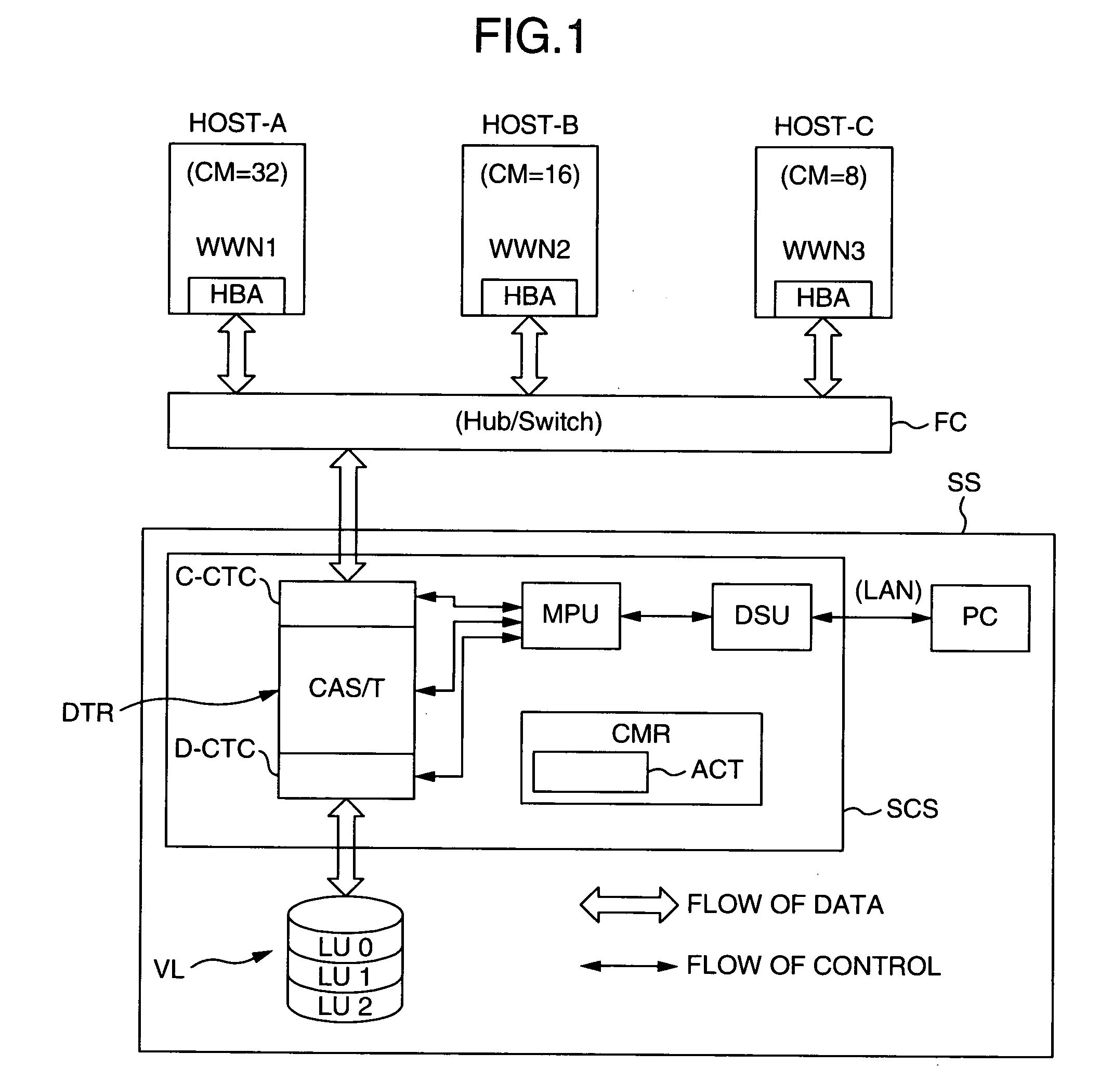
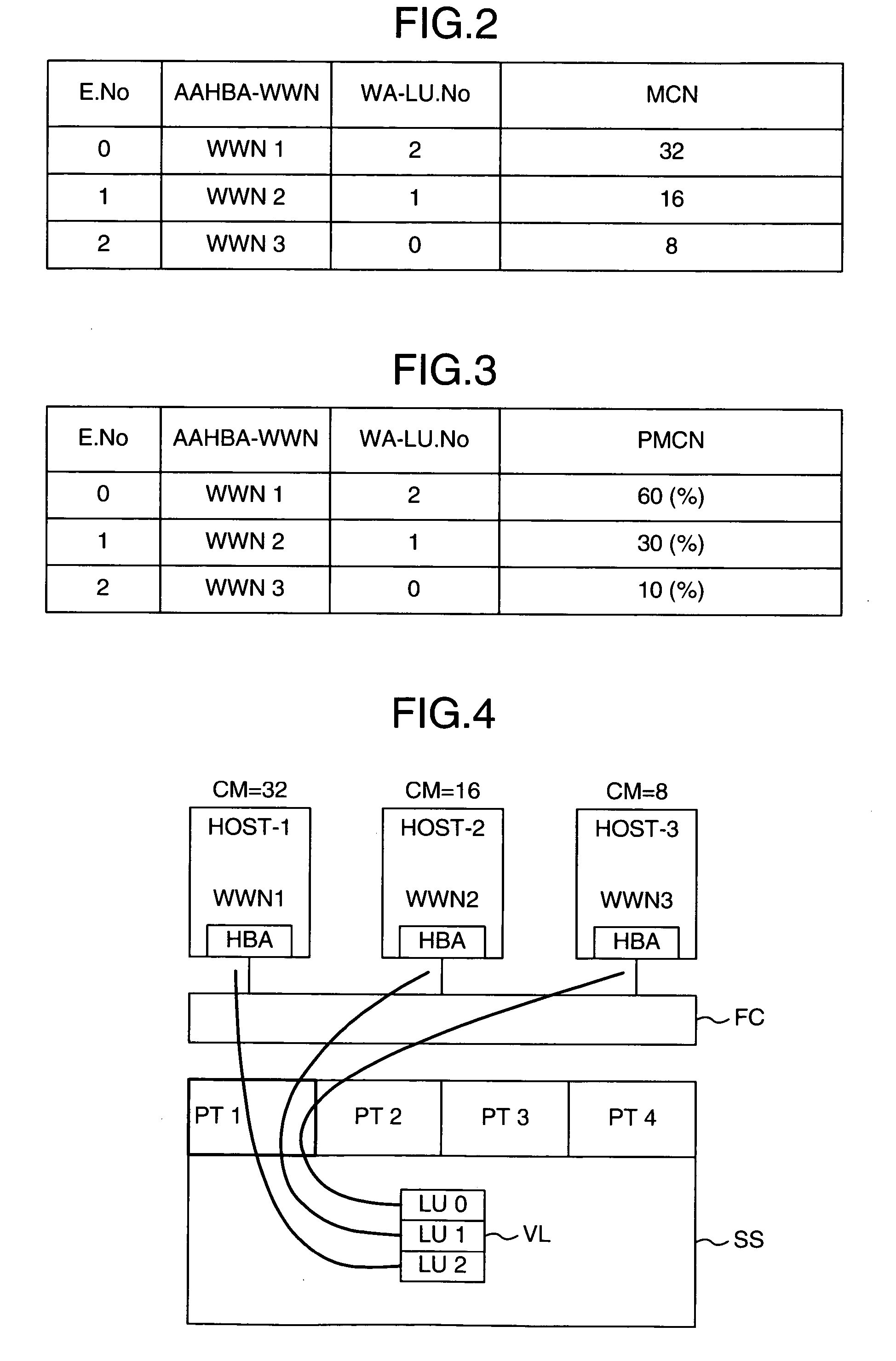
[0051] A first embodiment solves the following problem. FIG. 4 is a diagram of a computer system showing a first problem to be solved by the present invention. It is now supposed in FIG. 4 that three higher rank apparatuses HOST-1, HOST-2 and HOST-3 are connected to the storage apparatus SS via the fiber channel FC. It is supposed in FIG. 4 that the storage control apparatus includes four ports PT1, PT2, PT3 and PT4. Other components are not illustrated.

[0052] The higher rank apparatuses HOST-1, HOST-2 and HOST-3 are provided with, WWN1, WWN2 and WWN3, respectively. The command issue multiplex number CM is 32, 16 and 8, and the sum total (A) of the command issue multiplex numbers is 56.

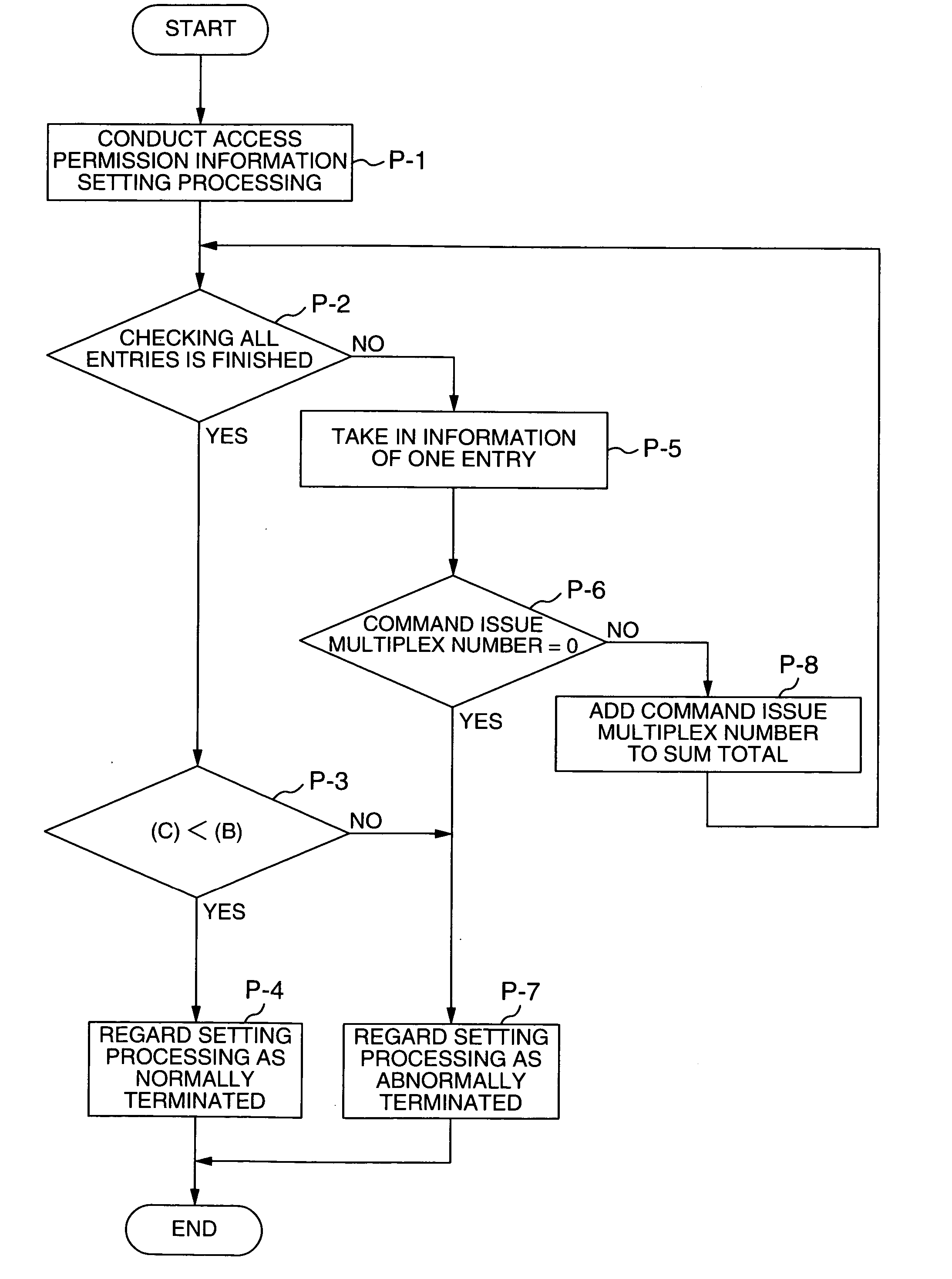
[0053] It is now supposed that the multiplex limit number of command processing in the port PT1 is (B). If the higher rank apparatuses HOST-1, HOST-2 and HOST-3 access the logical units LU1, LU2 and LU3 in the volume VL and the relationship represented as “the sum total (A) of the command issue mult...

second embodiment

[0060] A second embodiment solves the following problem. When setting the command issue multiplex numbers in the higher rank apparatuses in FIG. 5, there is a possibility that values different from the command issue multiplex numbers set in the storage apparatus SS together with the access permission will be set. In other words, it is necessary to set the command issue multiplex numbers set in the storage apparatus SS together with the access permission, in the higher rank apparatuses without fail. The second embodiment solves this problem.

[0061]FIG. 7 is a diagram of a computer system showing the second embodiment of the present invention. In the second embodiment, a reference instruction is used to be able to refer to the command issue multiplex number set in the storage apparatus from the higher rank apparatuses. As shown in arrows in FIG. 7, in response to a reference instruction (set value read instruction) from a higher rank apparatus, the storage apparatus SS, or the storage...

third embodiment

[0066] A third embodiment solves the following problem. When setting the command issue multiplex numbers in the storage apparatus SS shown in FIG. 5 together with access permission, there is a possibility that values different from the command issue multiplex numbers set in the higher rank apparatuses will be set. In other words, it is necessary to set the command issue multiplex numbers set in the higher rank apparatuses, in the storage apparatus together with the access permission without fail. The third embodiment solves this problem.

[0067]FIG. 9 is a diagram of a computer system showing the third embodiment of the present invention. In the third embodiment, a path management program incorporated in the higher rank apparatuses is referenced to find the command issue multiplex number, and the storage apparatus is referenced to find its value. A personal computer PC is connected to (a storage control apparatus SCS in) a storage apparatus SS and higher rank apparatuses HOST-1, HOST...


PUM


Abstract

There is provided a command multiplex number monitoring control scheme capable of avoiding issue of a QF status and getting rid of system performance degradation without adding command processing resources. Command issue multiplex numbers CMs (32, 16 and 8) for WWN1-LU2, WWN2-LU1 and WWN3-LU0 are set in a port PT1 so as to be associated with the host bus adaptors HBAs in higher rank apparatuses HOST-1, HOST-2 and HOST-3. Denoting the sum total of command issue multiplex numbers CMs for respective set access permissions by (C), an access permission satisfying the relationship represented as “command processing multiplex limit number (B)≧the sum total (C) of command issue multiplex numbers CMs for respective access permissions” is not permitted. Thus, the command issue multiplex numbers of the connected higher rank apparatuses are monitored.

Description

INCORPORATION BY REFERENCE [0001] The present application claims priorities from Japanese applications JP2004-111188 filed on Apr. 5, 2004, JP2004-142648 filed on May 12, 2004, the contents of which are hereby incorporated by reference into this application. BACKGROUND OF THE INVENTION [0002] The present invention relates to a command multiplex number monitoring control scheme in an information processing system including a plurality of higher rank apparatuses and a storage apparatus connected via a network, and a computer system using this command multiplex number monitoring control scheme. [0003] A storage apparatus connected to one or more higher rank apparatuses (hosts) via a storage area network (SAN) such as a fiber channel (FC) includes storage means (which is referred to as volume, and which typically includes a disk apparatus) having one or more logical units (LU) and a storage control apparatus for controlling the storage means. The storage control apparatus exercises cont...

Claims


Application Information

Patent Timeline
IPC IPC(8): G06F13/14G06F3/06G06F21/00H04L29/08
CPCG06F3/061G06F3/0637G06F3/0653G06F3/0659G06F3/067G06F21/805H04L49/90H04L67/1097
Inventor SHIRAKI, SHINJIRONAGATA, KOJI
Owner GOOGLE LLC
Why Eureka
Try Eureka